documentation
Hardware Overview
Recommended Operating Conditions
|
Item |
Minimum |
Maximum |
Unit |
|---|---|---|---|
|
Maximum supply voltage |
3 1 |
3.6 |
V |
|
Operating temperature |
-40 |
+85 |
degrees C |
|
Max current |
120 |
mA |
|
|
Idle current |
10.85 |
uA |
|
|
Maximum transmit output power |
+22 |
dBm |
|
|
Min RF input level for LoRa® detection SF7 BW 125kHz |
-127 |
dBm |
|
|
Min RF input level for LoRa detection SF12 BW 125kHz |
-140 |
dBm |
|
|
Min RF input level for GNSS detection |
-134 |
dBm |
|
|
Min RF input level for Wi-Fi b detection |
-92 |
dBm |
1 Limited by the ability of the battery to supply a transmit current of 110mA.
Architecture
The Semtech LoRa Edge™ Tracker Reference Design architecture has the following characteristics:
-
LR1110 Wi-Fi and GNSS capabilities
-
GNSS antenna diversity
-
Patch antenna
-
PCB antenna
-
-
STM32WB55 with BLE port configuration and update
-
2400 mAh battery
-
52 x 85 x 27 mm IP66 housing
-
LEDs
-
3-Axis & Hall Effect Sensors
-
Maximum transmit output power = +22 dBm
-
Typical sensitivity level:
-
LoRa:
-
-140 dBm at SF12 BW 125 kHz
-
-127 dBm at SF7 BW 125 kHz
-
-
GNSS: -134 dBm
-
Block Diagram
Figure 7: LoRa Edge Tracker Reference Design Block Diagram
-
The LoRa Basics™ Modem-E is an ultra-low power platform that integrates the following components:
-
Long-range LoRa transceiver
-
Multi-constellation scanner
-
Passive Wi-Fi AP MAC address scanner targeting asset management applications
-
-
The STM32WB55XX multi-protocol wireless and ultra-low power devices embed a powerful and ultra-low power radio, compliant with the Bluetooth® Low Energy SIG specification v5.0 and with IEEE 802.15.4-2011. They contain a dedicated Arm® Cortex® -M0+ for performing all real-time low-layer operations.
The control signals from/to the MCU and the LoRa Basics Modem-E are:
-
1 x SPI, coming from the MCU to the LoRa Basics Modem-E SPI interface
-
LoRa Basics Modem-E SPI interface Reset / Event / Busy line
-
1 x I2C, coming from the MCU to the accelerometer sensor I2C interface
-
GPIO for the Hall Effect sensor and user button
-
Control lines for SPDT:
-
Two from the MCU, for GNSS antenna diversity and Wi-Fi/BLE selection.
-
One from the LoRa Basics Modem-E, for LoRa RX/TX path selection.
-
Power Consumption
|
Mode |
Description |
Typical Current Consumption |
Unit |
|---|---|---|---|
|
Sleep mode without super cap |
10.85 |
μA |
|
|
Sleep mode with super cap |
18.85 |
μA |
|
|
Tx on at 22 dBm 915 mHz (HP_LF) |
TX Continuous |
134 |
mA |
|
Tx on at 14 dBm 868 MHz (HP_LF) |
TX Continuous |
86 |
mA |
|
TX BLE on at 0 dBm |
Advertisement |
11.1 |
mA |
|
Wi-Fi scan |
12.3 |
mA |
|
|
GNSS scan (Semi coherent research phase) |
15.2 |
mA |
|
|
GNSS scan (Coherent research phase) |
3.2 |
mA |
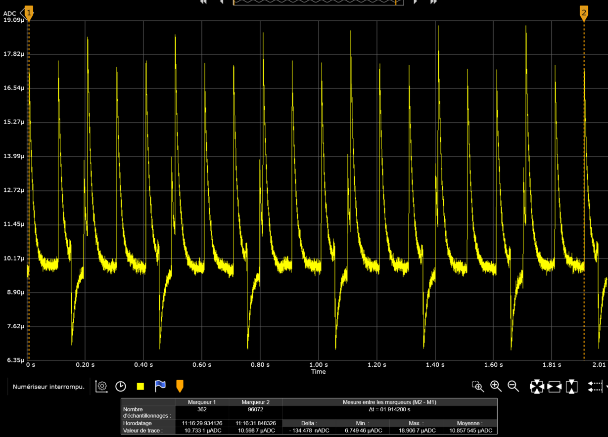
Power Consumption Profile
This chapter describes the typical power consumption profiles with standard parameter settings.
Note
The power consumption of the LoRa radio is not addressed here because it depends on the region where the tracker is deployed and the Adaptive Data Rate (ADR) strategy that is used.
Scan with Default Parameters
The power consumption profile has the following parameters:
GNSS Scan mode: Assisted
GNSS Search mode: Default
GNSS Antenna selection: Both
Wi-Fi Channels: Chan_1 / Chan_6 / Chan_11
Wi-Fi Nb retrials: 5
Wi-Fi Max result: 6
Wi-Fi Timeout: 90ms
Figure 8 shows the power consumption profile using the default accuracy parameters when the tracker is outdoors (For information on the scan strategy, see Tracker Application Capabilities.)
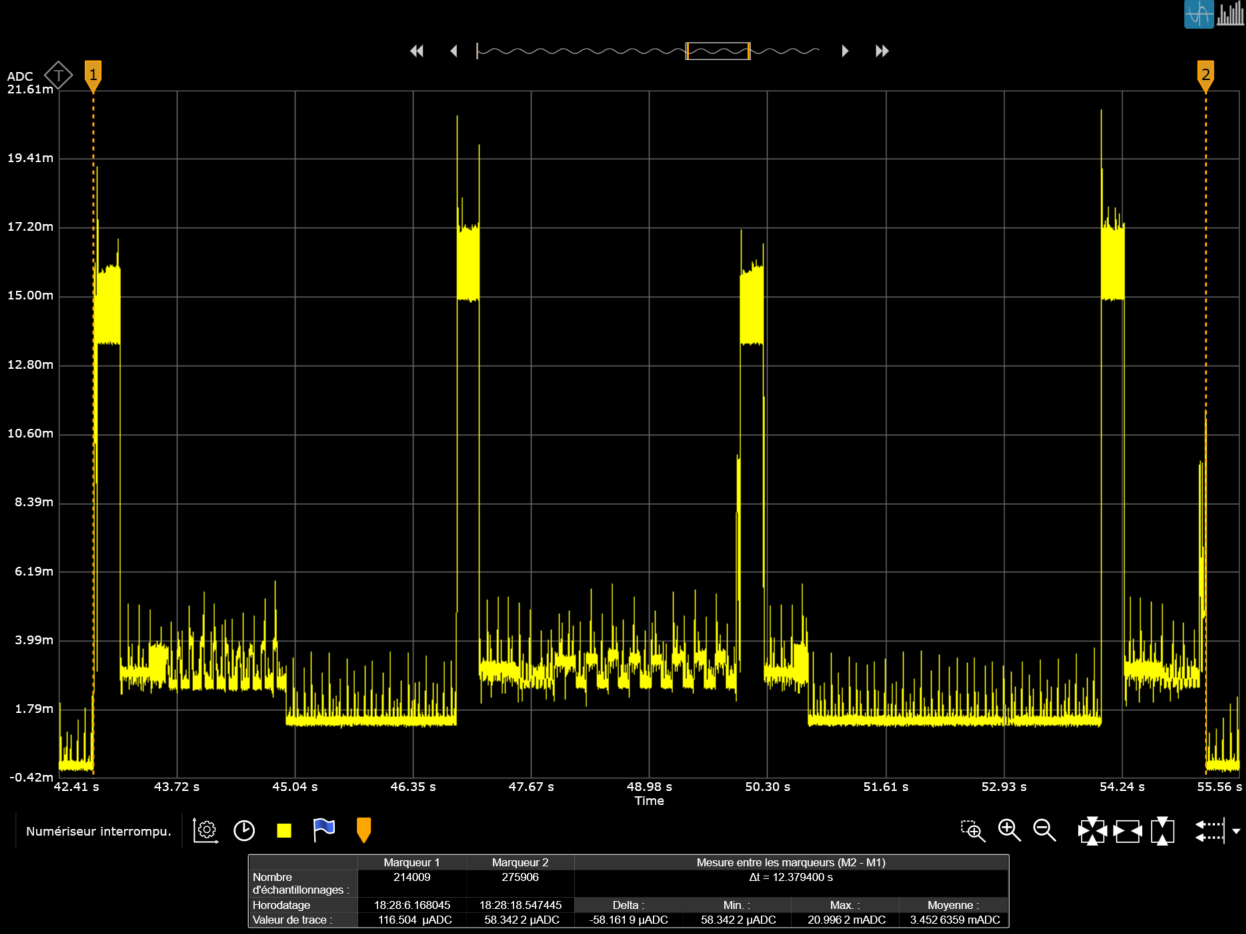
Figure 8: Power Consumption Profile Scan using the Default Parameters, outdoor case
The complete scan power consumption is about 3.45mA / 12.37 sec; therefore, 11.89μAh. If we split the power consumption by functionality, we get:
- GNSS Scan (x 2):
First scan (3.52mA / 7.16 sec), corresponding to 7μAh.
Second scan (3.29mA / 5.14 sec), corresponding to 4.7μAh.
Note
The power consumption varies depending on the number of GNSS satellites detected. If only one antenna is used, the consumption can be halved (depending on the environment).
Sensor readings (accelerometer / Hall Effect / charge): 8.53mA / 0.041 sec, corresponding to 0.09μA.
Figure 9 shows the power consumption profile using the default accuracy parameters when the tracker is indoors (For information on the scan strategy, see Tracker Application Capabilities.)
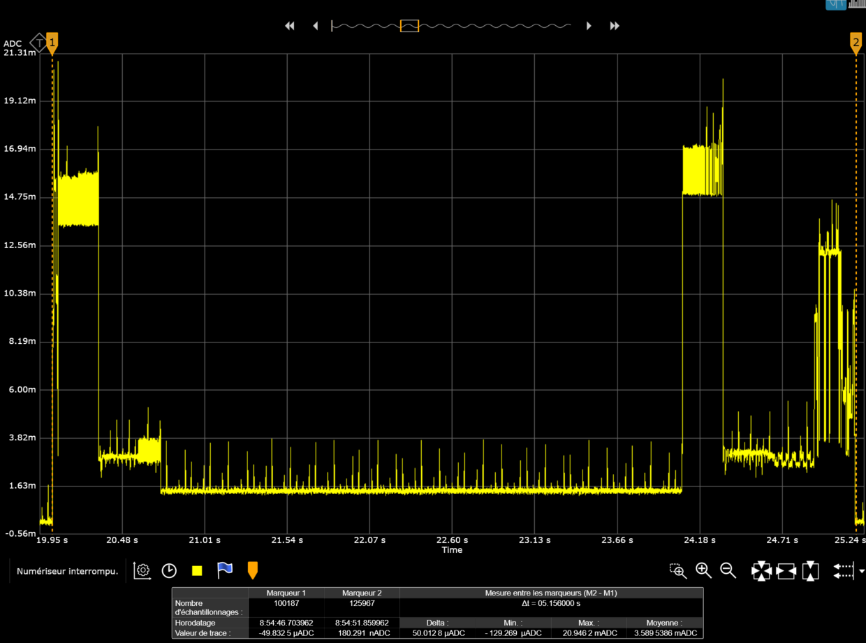
Figure 9: Power Consumption Profile Scan using the Default Parameters, indoor case
The complete scan power consumption is about 3.59mA / 5.14 sec; therefore, 5.13μAh. If we split the power consumption by functionality, we get:
GNSS Scan: (3.29mA / 4.88 sec), corresponding to 4.4μAh.
Wi-Fi: 10.08mA / 0.206 sec, corresponding to 0.57μAh.
Note
The power consumption varies depending on the number of Wi-Fi access points or GNSS satellites detected.
Sensor readings (accelerometer / Hall Effect / charge): 8.53mA / 0.041 sec, corresponding to 0.09μAh.
Antenna Performance
The antenna radiation patterns have been measured in a free space condition. The measurement setup and device orientation is shown in Figure 11.
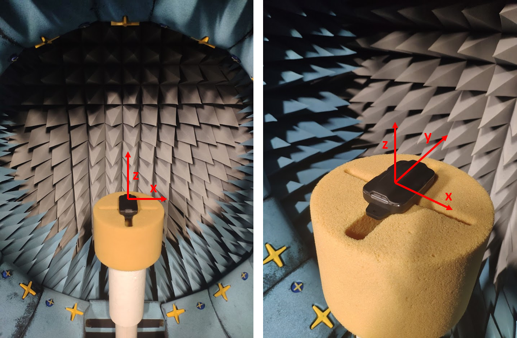
Figure 11: Radiation Diagram Measurement Setup
LoRa Antenna Radiation Pattern
The 3-D radiation pattern of the LoRa antenna of each tracker type (868MHz and 915MHz) has been measured at the antenna operating frequency, as shown in the following sections.
868MHz Antenna
The 3-D radiation pattern at 868MHz and the 2-D cuts in the various planes are shown in Figure 13, Figure 14, and Figure 15.
TRP = 11.83dBm
EIRP = 13.84dBm
Efficiency = 46%
Gain = -1.36dBi
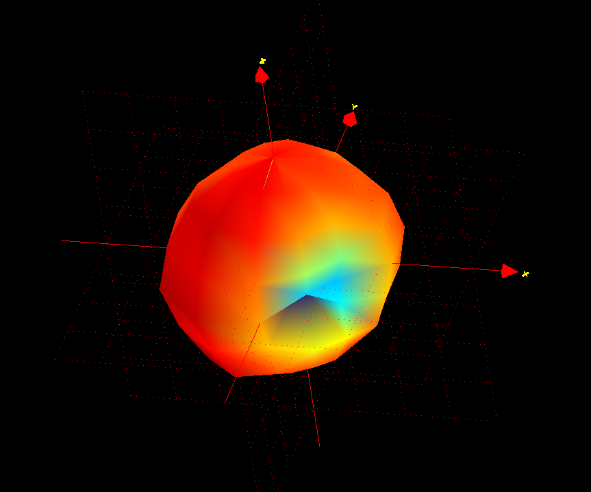
Figure 12: 3-D Pattern for Total Gain @ 868MHz
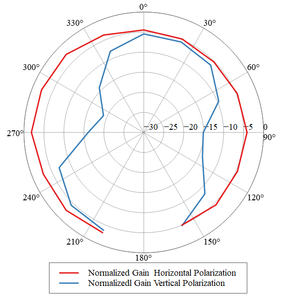
Figure 13: 2-D Radiation Pattern Planar Cut XoZ Plane @868MHz
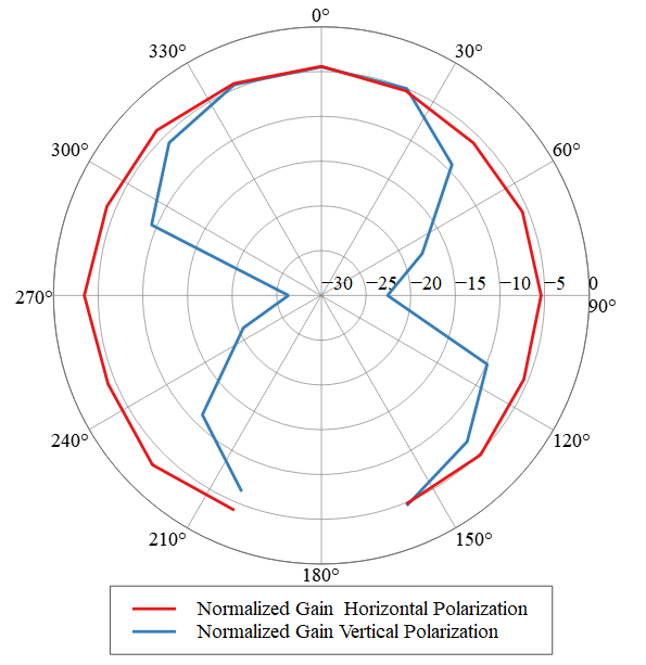
Figure 14: 2-D Radiation Pattern Planar Cut YoZ Plane @868MHz
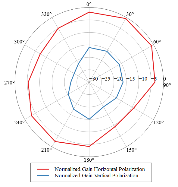
Figure 15: 2-D Radiation Pattern Planar cut XoY Plane @868MHz
915MHz Antenna
The 3-D radiation pattern at 915MHz is shown in Figure 16, whereas the 2-D cuts in the various planes are shown in Figure 17, Figure 18, and Figure 19.
TRP = 17.24dBm
EIRP = 19.41dBm
Efficiency = 40%
Gain = -1.73dBi
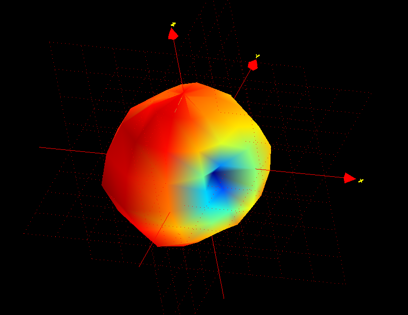
Figure 16: 3-D Pattern for Total Gain 915MHz
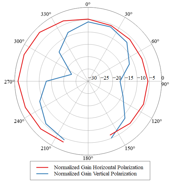
Figure 17: 2-D Radiation Pattern Planar Cut XoZ Plane @915MHz
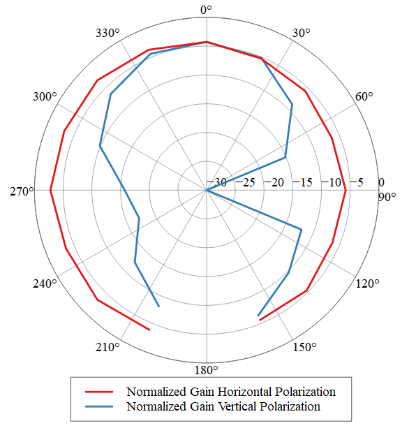
Figure 18: 2-D Radiation Pattern Planar Cut YoZ Plane @915MHz
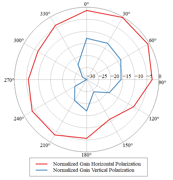
Figure 19: 2-D Radiation Pattern Planar Cut XoY Plane @915MHz
GNSS Antenna Radiation Pattern
The 3-D radiation pattern of the GNSS PCB antenna at 1.575GHz is shown in Figure 20.
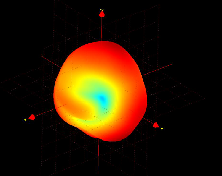
Figure 20: 3D Radiation Pattern of the GNSS PCB Antenna
2.4GHz Antenna Radiation Pattern
The 3-D radiation pattern of the 2.4GHz antenna at 2440MHz is shown in Figure 12, whereas the 2D cuts in the various planes are shown in Figures 21-24.
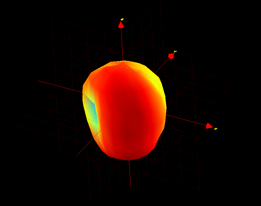
Figure 21: 3D Pattern for Total Gain @2440MHz
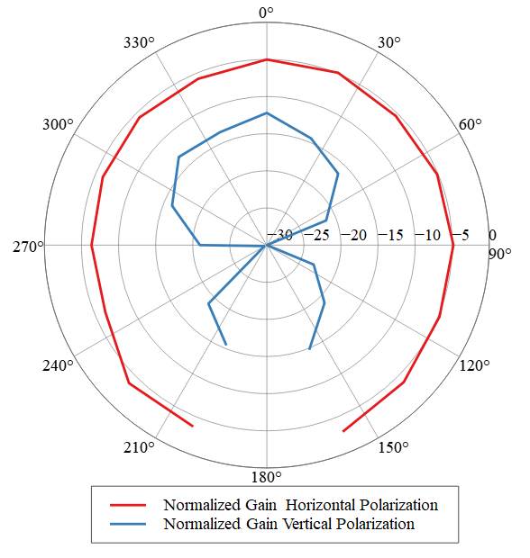
Figure 22: 2-D Radiation Pattern Planar Cut XoZ Plane @2440MHz
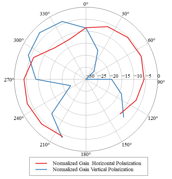
Figure 23: 2-D Radiation Pattern Planar Cut YoZ Plane @2440MHz
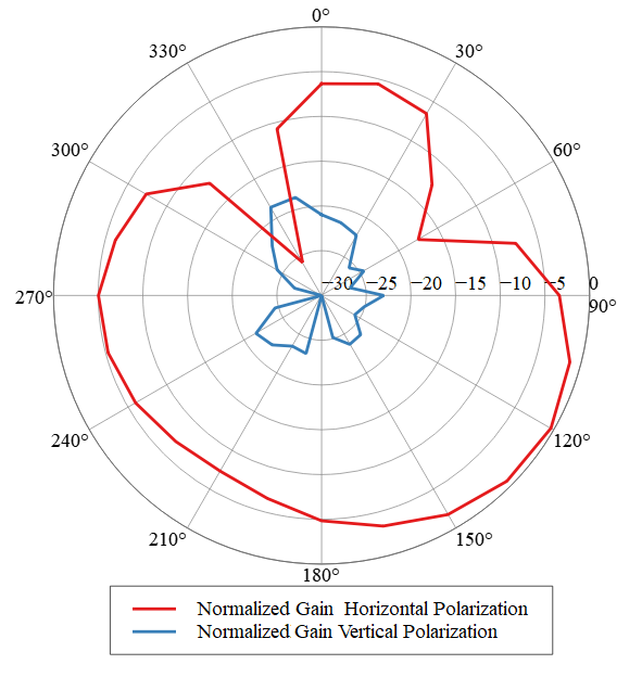
Figure 24: 2-D Radiation Pattern Planar Cut XoY Plane @2440MHz
QR Code Description
The QR code printed on the device label integrates the Device ID in the QR code, as defined by the LoRa Alliance®.

Figure 25: EU Label
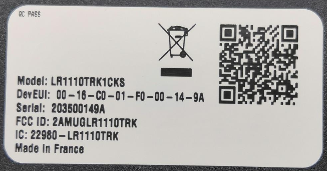
Figure 26: U.S. Label
The QR code contains the following information:
Preface: LW
SchemaID: D0
JoinEUI: (00-16-C0-01-FF-FE-00-01 in this example)
DevEUI: (00-16-C0-01-F0-00-14-9A in this example)
ProfileID: 016A-0001
OwnerToken: 4A21235D: pin of the LoRa Basics Modem-E
SerNum of Mfg Serial Number: YYWWNNNNNN (Year, Week, Serial Number)
Proprietary: US915 (for U.S.), EU868 (for EU)
CheckSum: (CRC-16/MODBUS)
- The information contained in the QR code represents 58 bytes of data:
-
LW:D0:0016C001FFFE0001:0016C001F000149A:016A0001:O4A21235D:S2126220290:PEU868
- With the CRC, we have 64 bytes of data:
-
LW:D0:0016C001FFFE0001:0016C001F000149A:016A0001:O4A21235D:S2126220290:PEU868:C7ECF
For more information, see TR005 LoRaWAN® Device Identification QR Codes.