documentation
An In-depth look at LoRaWAN® Class A Devices
Introduction
A LoRaWAN®-based network is made up of end devices, gateways, a network server, and application servers. End devices send data to gateways (uplinks), and the gateways pass it on to the network server, which, in turn, passes it on to the application server as necessary.
Figure 1: Uplink Transmission
![]()
Additionally, the network server can send messages (either for network management, or on behalf of the application server) through the gateways to the end devices (downlinks).
Figure 2: Downlink Transmission
![]()
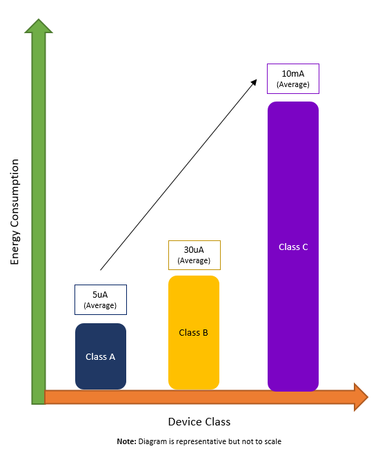
End devices in a LoRaWAN network come in three classes: Class A, Class B and Class C. While end devices can always send uplinks at will, the device’s class determines when it can receive downlinks. The class also determines a device’s energy efficiency. The more energy efficient a device, the longer the battery life.
All end devices must support Class A (“Aloha”) communications. Class A end devices spend most of their time in sleep mode. Because LoRaWAN is not a “slotted” protocol, end devices can communicate with the network server any time there is a change in a sensor reading or when a timer fires. Basically, they can wake up and talk to the server at any moment. After the device sends an uplink, it “listens” for a message from the network one and two seconds after the uplink (receive windows) before going back to sleep. Class A is the most energy efficient and results in the longest battery life.
In contrast, rather than only waiting for one of its sensors to notice a change in the environment or fire a timer, Class B end devices also wake up and open a receive window to listen for a downlink according to a configurable, network-defined schedule. A periodic beacon signal transmitted by the network allows those end devices to synchronize their internal clocks with the network server.
Finally, Class C (“Continuous”) end devices never go to sleep. They constantly listen for downlink messages from the network, except when transmitting data in response to a sensor event. These devices are more energy-intensive, and usually require a constant power source, rather than relying on a battery.
To illustrate the different levels of power consumption for each of the different end-device classes, see Figure 3.
Figure 3: Energy Consumption by Device Class
In this paper, we take an in-depth look at Class A end devices.
Understanding Class A End Devices
The LoRaWAN protocol relies on an Aloha-type network. In this type of network, end devices are allowed to transmit arbitrarily.
The key characteristic of Class A is that communication is initiated only by the end device.
Downlink messages from the network server are queued until the next time an uplink message is received from the end device and a receive window (Rx) is opened. This design is specifically geared toward applications that require downlink communication in response to an uplink, or that can schedule downlinks ahead of time with fairly loose latency requirements.
Receive Windows
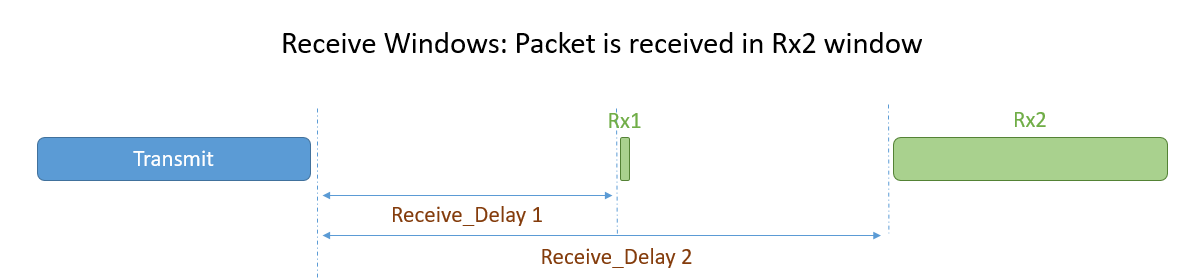
Following an uplink, a Class A end device opens a short receive window (Rx1) and, if no downlink is received during that period, it opens a second receive window (Rx2). The start time of Rx1 begins after a fixed amount of time following the end of the uplink transmission. Typically, this delay is one second, however this duration is configurable. Rx2 typically begins two seconds after the end of the uplink transmission, though this duration is also configurable. The following diagrams illustrate the different receive window state possibilities.
Figure 4: Nothing is received

Figure 5: Packet received in Rx1 window
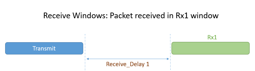
Figure 6: Packet received in Rx2 window
The default delay for Rx1 (RECEIVE_DELAY1) is a network parameter found in the LoRaWAN Regional Parameters document from the LoRa Alliance®. The default delay may be region-specific, and can be changed by the network operator through the MAC command RxTimingSetupReq. It is typically set to one second
The end device then waits one second after Rx1 closes before opening Rx2. This means that RECEIVE_DELAY2 = RECEIVE_DELAY1 + one second.
Note: A device will not try to send another uplink message until either:
- It has received a downlink message during Rx1, or
- The second receive window following the last transmission is complete
Transmission Frequencies and Data Rates
The frequency used for Rx1 is a function of the uplink frequency. The data rate it uses is a function of the data rate used for the uplink transmission. The default relationship between the uplink frequency and the Rx1 downlink frequency and data rate are defined in the LoRaWAN Regional Parameters document. The default parameters can be remotely reconfigured by the network operator using the relevant LoRaWAN MAC commands.
Rx2 uses a frequency and data rate that can be configured using a MAC command. The defaults are region-specific.
MAC Commands
With respect to Rx1, the offset between the uplink transmission (Tx) data rate and the downlink data rate can be configured using the Rx1DRoffset field of the RxParamSetupReq MAC command
To configure the Rx2 data rate, use the MAC command RxParamSetupReq.
The DiChannelReq MAC command allows the network to associate a different downlink frequency with the Rx1 window. This command works for all regions that support the NewChannelReq MAC command. For example, DiChannelReq applies in the EU and in China, but not in the U.S. or Australia, as described in the LoRaWAN Regional Parameters document.
Class A Energy Profile
The duration of each receive window must be at least as long as the time required by the end device’s radio transceiver to effectively detect a downlink preamble. If the device detects a downlink preamble during this time, the radio receiver will stay open until the downlink data is demodulated.
If a downlink was detected and demodulated during Rx1 and if, (after the address and Message Integrity Check (MIC)) it is determined to be intended for the end device that received it, the device will not open Rx2 in an attempt to conserve energy. However, if the end device does not receive a downlink message during Rx1, it will continue to open Rx2 on schedule.
When there is nothing for an end device to receive, it will still open its reception windows, but just long enough to determine whether there is a preamble. At minimum, this is 5.1 milliseconds (ms) at a data rate of SF7. At maximum, it is 164 ms at a data rate of SF12. If, on the other hand, there is a downlink coming to the device, at SF7, it will take less than 100 ms to demodulate the message. At SF12 it can take more than two seconds.
Figure 7: Uplinks, Downlinks and Wake-up Times for SX126x Radios
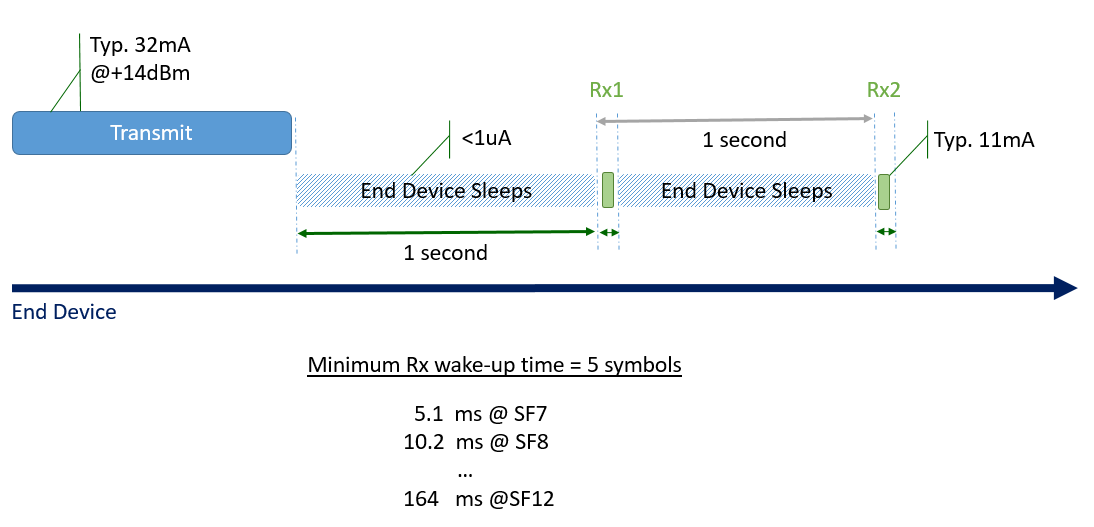
The energy drain linked to Rx1 and Rx2 when no downlink message is detected is negligible compared to the energy required for the transmission of the uplink
LoRaWAN Network Topology
Figure 8 illustrates the LoRaWAN network topology. The key difference between the LoRaWAN approach and others is that end devices are paired with the network itself and are not exclusively tied to a single gateway. Rather, end devices broadcast their signals to all gateways within range. Each of the receiving gateways pass the data packet along to the network server, and then the network server de-duplicates the message and sends a single version of it to the application server.
Figure 8: LoRaWAN Network Topology
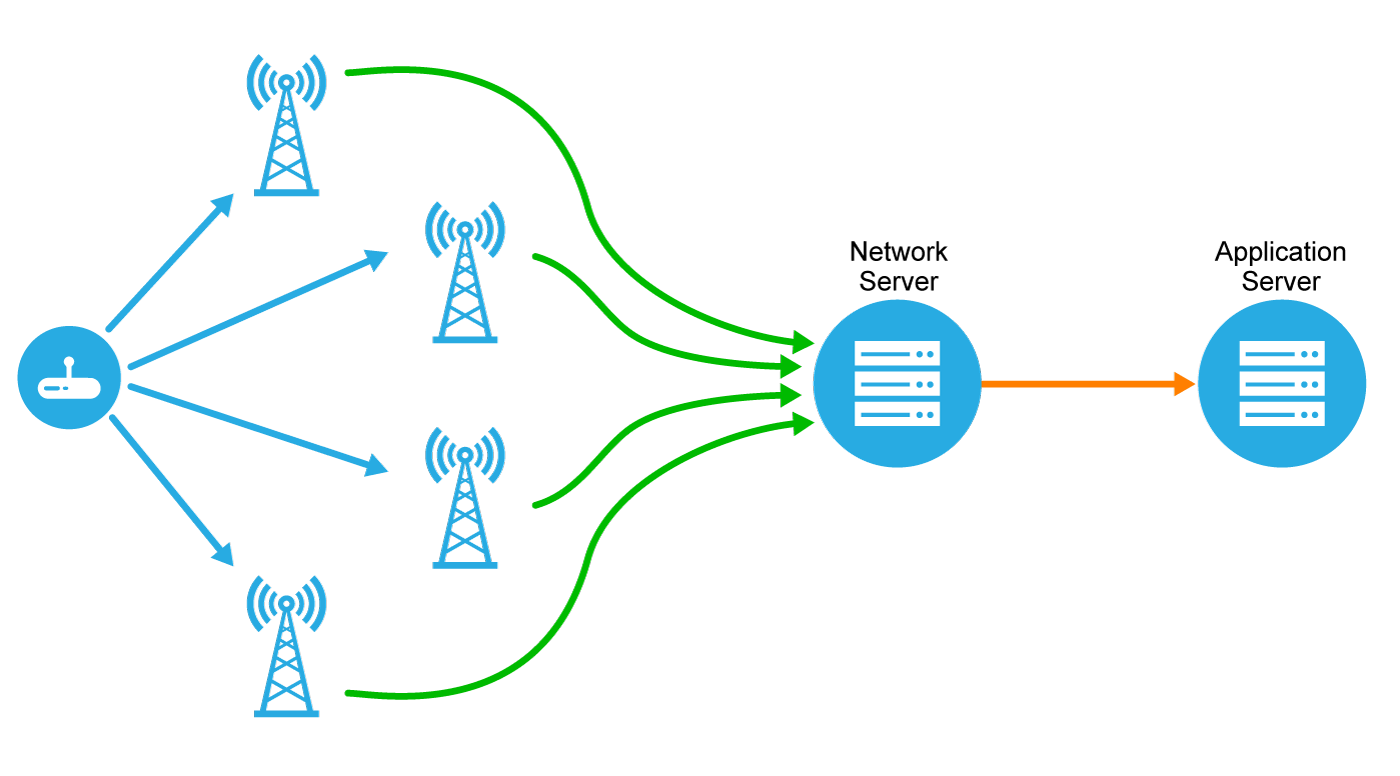
There are several advantages to this topology:
- No complicated network planning is required. Gateways can be added anywhere at any time.
- Accurate message delivery is more robust, since multiple gateways receive the same data packet during each uplink. This is called uplink spatial diversity.
- There is no need to plan for different frequencies for each gateway, or to reallocate frequencies when the number of gateways change. All gateways are constantly listening to all frequencies of the network.
- Mobile devices can operate at low power thanks to the fact that any gateway can receive messages from any device. This means that (in contrast, for example, to Cellular networks) the LoRaWAN network does not notice or care that the device is moving; it simply receives uplinks from the gateways nearest the device’s current location.
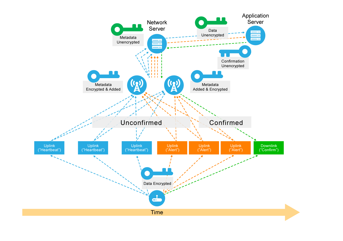
Unconfirmed and Confirmed Messaging
Messages from end devices to the network and application servers and vice versa may be unconfirmed or confirmed.
When a device sends an unconfirmed message, it does not require an acknowledgement from the server. For example, most of the time a smoke detector will send periodic, unconfirmed uplinks to the network server via nearby gateways just to confirm that it is working. The gateways receive the data and pass it on to the network server, which in turn passes it on to the application server.
When sending a confirmed message, the end device requires that the message be acknowledged as received by the network server. Let’s look at our smoke detector again. When the smoke detector detects something, it will continue to transmit alerts that need to be confirmed until the alert is acknowledged. The acknowledgement informs the smoke detector that someone is responding to the alert. Because downlinks from the network are a scarce resource, they should be used sparingly. Confirmed messages should be used only for very important sensor data.
Figure 9 shows a smoke detector transmitting encrypted, unconfirmed messages (see the arrows pointing from the device at the bottom of the diagram up to the Application Server at the top via the three leftmost boxes), which are received by two gateways. The gateways add encrypted metadata to the messages and then forward them to the network server. The network server decrypts the metadata and sends the data packet to the application server, which decrypts the data.
In orange, we see the smoke detector sending an alert. These are confirmed messages, however, in the first two instances, no acknowledgement has been received, so the device continues to broadcast the alert. Finally, after the third transmission of the alert in our example below, the application server sends an acknowledgement to the device via the network server and the most appropriate gateway.
Figure 9: Unconfirmed and Confirmed Messaging
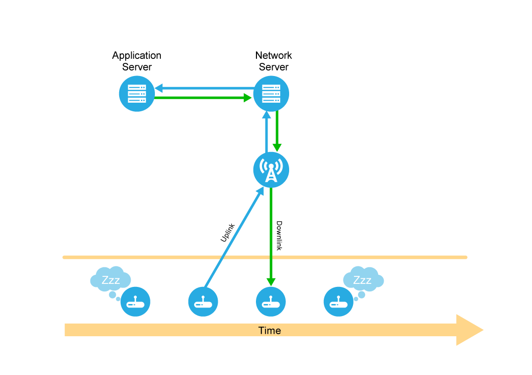
Application Server Downlinks
In this next example, the smoke detector application server has data to transmit to a specific, sleeping, smoke detector (the end device). However, since the smoke detector is a Class A device, the application server has to wait until the smoke detector wakes up before the server can send the data. For smoke detectors, this is a periodic message (e.g., sent every 8 hours) sharing status information—like battery status—with the application server and not a real smoke-detection event. Receipt of this message by the end device may be either confirmed or unconfirmed. Take a look at Figure 10. Here, the application server has data to send to the smoke detector, but the device is asleep. The server must wait for an uplink from the device before it can send its data. As soon as the uplink is received, the application server immediately transmits the downlink. In the case of an unconfirmed message of this sort, upon receipt of the downlink, the device goes back to sleep.
Figure 10: Application Server Downlink
Summary
In short, all end devices must support Class A operation, which is the most energy efficient mode of communication and supports the longest battery life. Class A end devices stay in deep-sleep mode until they sense a change in their environment or some other event is triggered. When this occurs, the affected device wakes up and sends its data to the network server (and eventually the application server) via one or more gateways. Following the uplink transmission, the end device will open two consecutive receive windows, during which they listen for potential downlink transmissions from the server.