documentation
In-Depth: LoRaWAN® End Device Activation
This paper covers LoRaWAN® end-device activation in depth. It is aimed at end device software developers and managers of teams building devices with LoRa® that implement the LoRaWAN Link Layer Specification v1.0.4. This paper helps you gain a deep understanding of how end-device activation works, the options available and best practices.
Already using software such as LoRaMAC-Node™ to handle end-device activation? This article gives you the background you need to understand how the software is working, review the code, and gain confidence that your end device is following the standards and best practices defined in the LoRaWAN Link Layer Specification.
End-Device Activation Options
All end devices that participate in a LoRaWAN network must be activated. There are two methods of activation you can choose: over-the-air activation (OTAA) or activation by personalization (ABP).
The OTAA and ABP activation methods each result in secret session keys being held by both the end device and the network server, which are used to secure messages being sent and received across the network. In ABP, these session keys are stored on the end device during the manufacturing process. In OTAA, the session keys are generated during a series of exchanges with the network server.
OTAA is the more secure option, since the keys can be replaced at any time by rejoining the network. The network server also supplies settings to the end device during the OTAA join procedure to optimize ongoing communications between the network server and the end device.
Implement OTAA unless you have a strong reason for not doing so.
Data Stored in End Device After Activation
Three pieces of data are set on the device by the activation process: the Network Session Key (NwkSKey), Application Session Key (AppSKey), and end device address (DevAddr). These are generated and stored when the device first attempts to connect to the network through the OTAA process for devices implementing OTAA, or are stored directly in the device at time of manufacturing for devices implementing ABP.
Network Session Key (NwkSKey)
The network server and end device both use the Network Session Key (NwkSKey) to verify the integrity of all data frames. In addition, the NwkSKey is used by both the network server and the end device to encrypt and decrypt MAC commands sent as MAC-only data frames.
Use of the NwkSKey for Integrity Verification
Every LoRaWAN uplink or download packet contains a 4-octet message integrity code (MIC) within the PHY Payload, as shown in Figure 1.
Calculate the MIC over the Mac Header (MHDR), Frame Header (FHDR), Frame Port (FPort), and Frame Payload (FRMPayload) using the NwkSKey following the instructions in section 4.4, Message Integrity Code specification (page 25) of the TS001-1.0.4 LoRaWAN® L2 1.0.4 Specification.
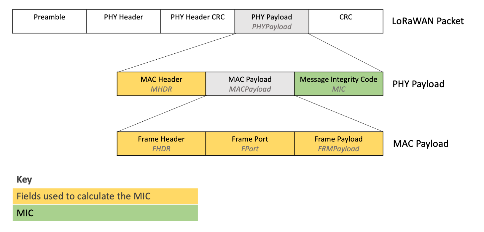
Figure 1: MIC within the PHY Payload, and the fields used to calculate the MIC
Calculate the MIC using the NwkSKey when sending uplinks from the end device. The network server verifies the MIC using the same NwkSKey.
Verify the MIC using the NwkSKey when receiving downlinks from the network server.
Verifying the MIC ensures that the data has not been tampered with.
Use of the NwkSKey for Encryption of MAC-Only Data Frames
MAC commands sent in the Frame Payload (FRMPayload) where the Frame Port (FPort) is set to 0 are MAC-only data frames, as shown in Figure 2. MAC-only data frames are encrypted using the NwkSKey.
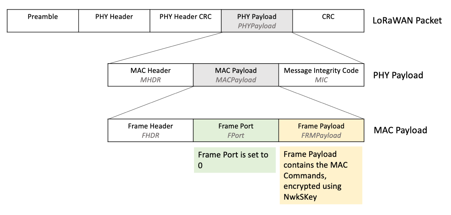
Figure 2: MAC Payload where FRMPayload contains MAC commands, with FPort set to 0
Encrypt and decrypt the FRMPayload using the NwkSKey following the instructions in section 4.3.3, MAC frame payload encryption specification (page 24) of the TS001-1.0.4 LoRaWAN® L2 1.0.4 Specification.
Encrypt the FRMPayload using the NwkSKey when sending MAC-only data frame uplinks from the end device.
Decrypt the FRMPayload using the NwkSKey when receiving MAC-only data frame downlinks from the network server.
Encrypting the FRMPayload provides security and prevents anyone from inspecting these messages.
Read more about MAC-only data frames in the Sending and Receiving MAC Commands section of our paper A Deep Dive into LoRaWAN® MAC Commands.
Warning
When you encrypt the FRMPayload, ensure that you calculate the MIC after encryption, using the encrypted FRMPayload. If you calculate the MIC on the unencrypted FRMPayload, the MIC verification will fail.
Application Session Key (AppSKey)
The application server and end device use the AppSKey to encrypt and decrypt the Frame Payload (FRMPayload) field of application-specific data frames.
Note
The application server is referred to separately from the network server in the LoRaWAN 1.0.4 specification. The messages are first sent from the end device to the network server. Internally, the network server then passes the frame payload of application-specific data frames to an application server.
One benefit of separating the network server and application server is that the network server does not need to know the AppSKey and thus cannot decrypt the application messages.
Learn more about the separation of network server and application server in TS2-1.1.0 LoRaWAN Backend Interfaces Specification.
Use of the AppSKey for Encryption of Application-Specific Data Frames
Application-specific data frames are data frames sent where the Frame Port (FPort) is set between 1 and 255, indicating that the Frame Payload (FRMPayload) contains application data as shown in Figure 3. Application-specific data frames contain data specific to the end device use case, such as temperature readings for a temperature sensor.
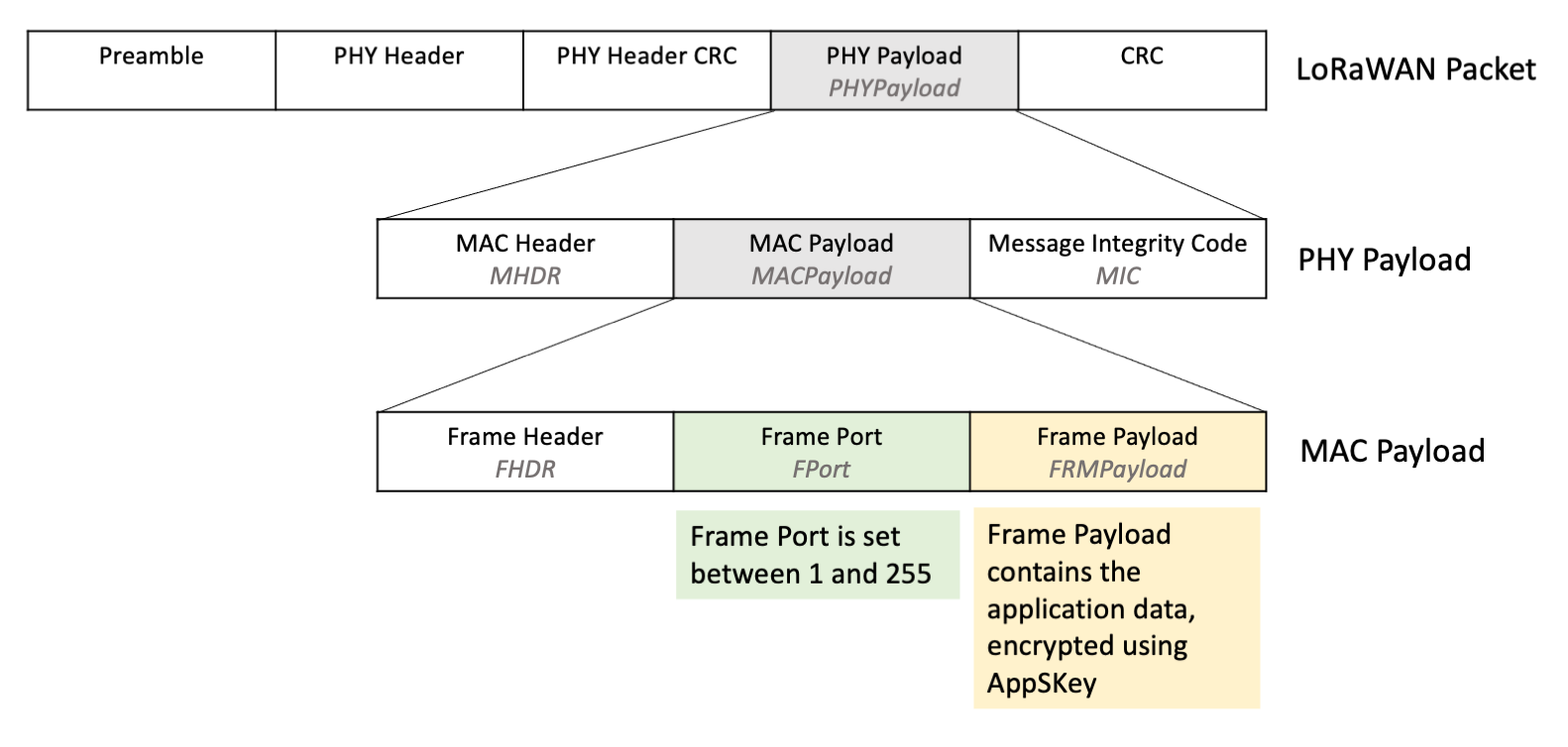
Figure 3: MAC Payload where FRMPayload contains application-specific data, with FPort set between 1 and 255
Encrypt and decrypt the FRMPayload in application-specific data frames using the AppSKey following the instructions in section 4.3.3, MAC frame payload encryption specification (page 24) of the TS001-1.0.4 LoRaWAN® L2 1.0.4 Specification.
Encrypt the FRMPayload using the AppSKey when sending application-specific data frame uplinks from the end device.
Decrypt the FRMPayload using the AppSKey when receiving application-specific data frame downlinks from the network server.
Encrypting the FRMPayload provides security and prevents anyone from inspecting these messages.
Warning
When you encrypt the FRMPayload, ensure that you calculate the MIC after encryption, using the encrypted FRMPayload. If you calculate the MIC on the unencrypted FRMPayload, the MIC verification will fail.
Device Address (DevAddr)
The Device Address (DevAddr) is a 32-bit identifier allocated by the network server. The DevAddr is used with the NwkSKey to identify the device in the current network.
Warning
It is possible for a network server to allocate the same DevAddr to multiple devices. This does not cause any issues on the network server because the network server identifies the device using the combination of DevAddr and NwkSKey, and the NwkSKey is unique to each device. Use the Device EUI (DevEUI) to uniquely identify your devices in your own applications; this is fixed and will not change when you move the device between networks.
Over-the-Air Activation (OTAA) Device Provisioning
OTAA is the most secure method of connecting to the network server. In this section we explain the OTAA process in full, as shown in Figure 4, from setting the initial keys through the join procedure and sending the first message.
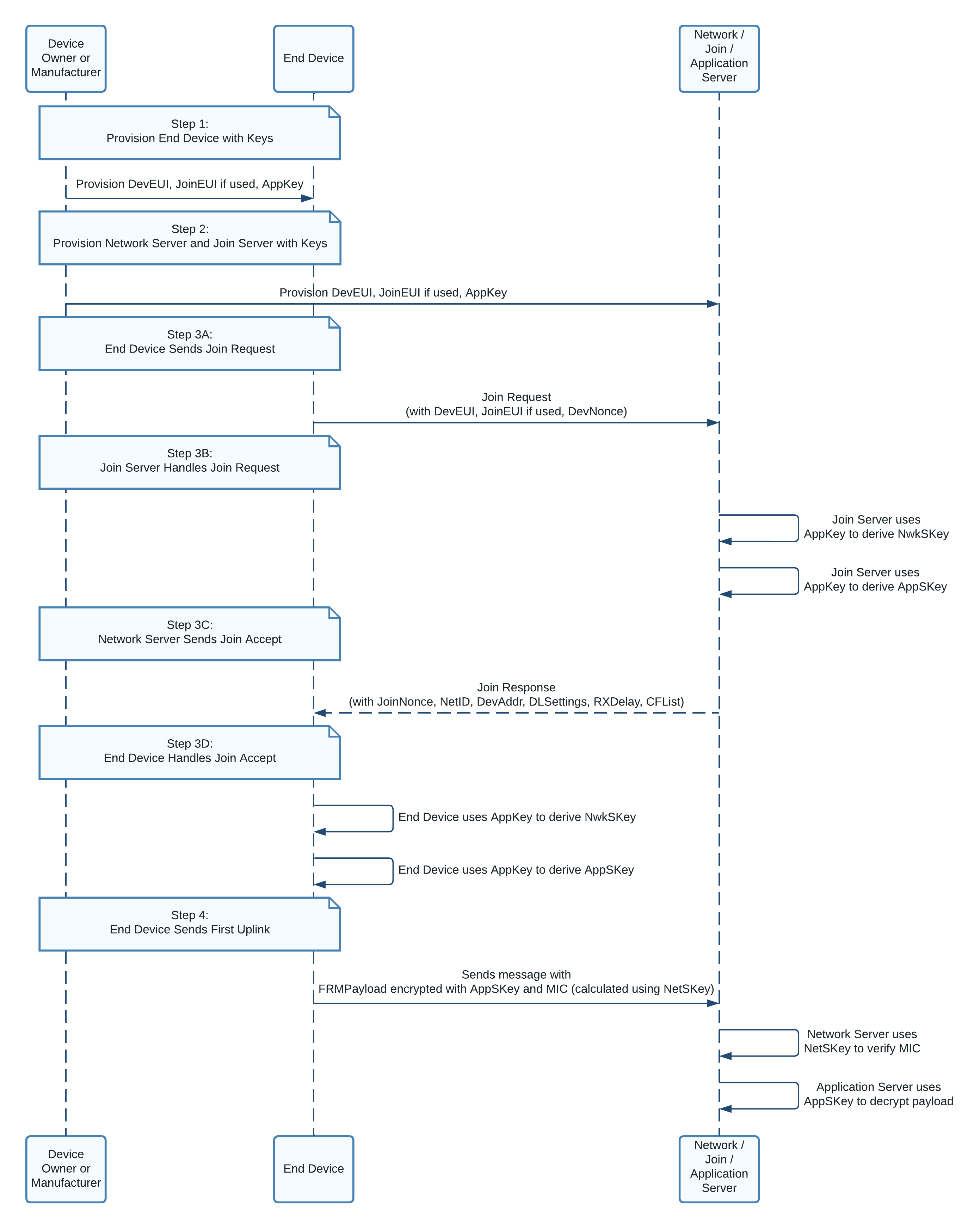
Figure 4: Sequence diagram showing the transfer of data between device owner, end device, and network server.
Step 1: Provision End Device with Keys
The following keys must be provisioned (stored) on the end device in non-volatile memory (NVM) when the device is manufactured: Device Extended-Unique-Identifier (DevEUI), Join Extended-Unique-Identifier (JoinEUI), and Application Key (AppKey).
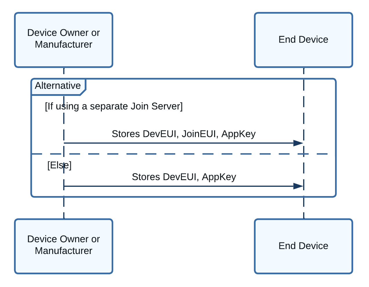
Figure 5: Sequence diagram showing the keys provisioned on the end device
You are responsible for obtaining these keys as described in this section.
Note
A good practice is to print the DevEUI on the cover of the end device to ease device management. Document TR005 LoRaWAN Device Identification QR Codes explains how to generate a QR code containing the DevEUI and JoinEUI. Never include the AppKey in this QR code, and never show it on the cover of the end device.
Device EUI (DevEUI)
The DevEUI is a globally unique 64-bit identifier in the Institute of Electrical and Electronics Engineers (IEEE) EUI-64 address space that uniquely identifies the end device.
The manufacturer of the radio module may have already provisioned the module with a valid DevEUI. If not, or if you cannot use the provisioned DevEUI, you must obtain your own globally unique DevEUI. Learn about obtaining a DevEUI for commercial use by reading section 2.2, Extended-Unique Identifier (page 7) and section 2.5.1, Device EUI (page 8) of TR007 Developing LoRaWAN® Devices V1.0.0. Further advice on obtaining a DevEUI is found in Developing LoRaWAN-based Devices: Things to know, DevEUI.
Warning
It is essential that you obtain unique addresses for your devices when you put them into production. Do not invent your own DevEUIs. Once one of your devices has been shipped to a customer, it can be joined to any network; if another device on the network already uses the same DevEUI as your device, your customer won’t be able to add your device to their network.
In addition, use of a globally unique identifier enables your device to use LoRaWAN roaming. If supported by the network server your end device is registered with, roaming enables the use of gateways provided by other network servers which participate in a roaming scheme with your own network provider. Learn more about roaming in section 11, Roaming Procedure (page 22) of LoRaWAN® Backend Interfaces Technical Specification (TS002-1.1.0).
Join Server Identifier (JoinEUI)
The Join Server Identifier (JoinEUI) allows support for use of a join server that is separate from the network server, providing an additional layer of security whereby it is not possible for the network server to access the AppSKey and therefore the network server is unable to decrypt the application-specific messages sent to and from the device. Learn more about the separation of network server and join server in TS2-1.1.0 LoRaWAN Backend Interfaces Specification.
The JoinEUI is an identifier in the Institute of Electrical and Electronics Engineers (IEEE) EUI-64 address space that identifies which join server to use to handle the join process. This join server must be provisioned with the device’s AppKey and DevEUI before the join process begins.
The JoinEUI is supplied to you by the operator of the join server you are using. Many devices will use the same JoinEUI.
If you are not using a join server separately from the network server, choose one of the EUIs that you own to be the JoinEUI to use across all your devices. Using a valid EUI as the JoinEUI will enable you to use an external Join Server in the future.
Warning
Do not invent your own JoinEUI. Do not generate a unique JoinEUI for each device.
Note
In LoRaWAN Link Layer Specifications prior to 1.0.4, JoinEUI is referred to as AppEUI.
Application Key (AppKey)
The application key (AppKey) is an Advanced Encryption Standard (AES) 128-bit root key unique to the end device. The AppKey is used by both the end device and the join server to derive the NwkSKey and AppSKey session keys during the OTAA process, and to verify the integrity of the join request and join accept messages sent during the OTAA process as part of the MIC.
Read section 2.5.3, Root Keys (page 9) of TR007 Developing LoRaWAN® Devices V1.0.0 to learn how to securely generate and store root keys such as the AppKey.
Step 2: Provision Network Server and Join Server with Keys
Before you initiate the OTAA join process, you must register keys with the network server and, if in use, the join server. The process depends on whether you use a separate join server or not.
If you are using a separate join server:
-
Register the device on the join server, providing the DevEUI and AppKey.
-
You or your customer will register the device on the network server with the DevEUI, AppKey, and JoinEUI prior to initiating the join process described below.
If you are not using a separate join server:
-
You or your customer will register the device on the network server with the DevEUI and AppKey prior to initiating the join process described below.
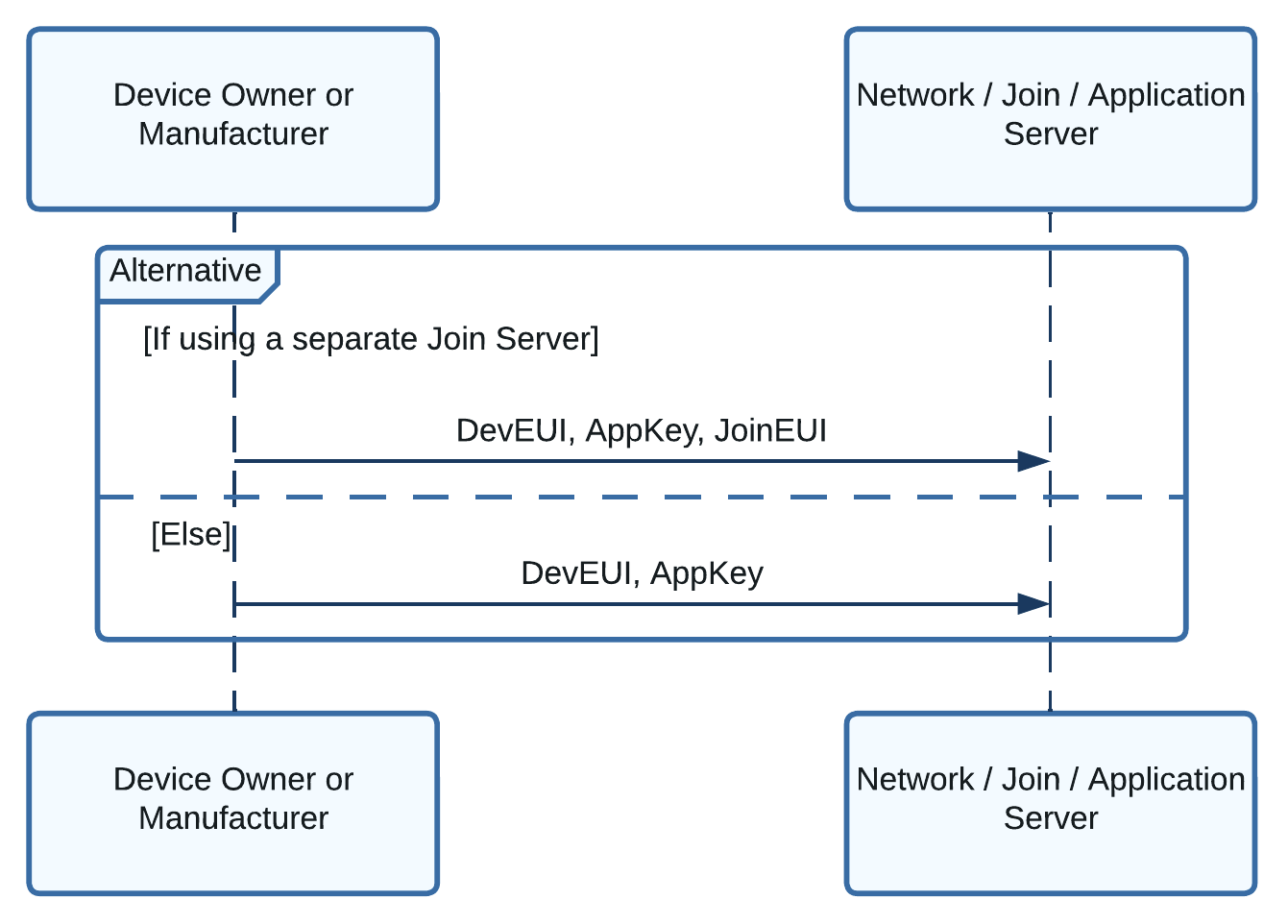
Figure 6: Sequence diagram showing the keys provisioned on the network server and optional join server
Note
If your network server has a required field of JoinEUI or AppEUI and you are not using a separate join server, set this value to the JoinEUI you defined on your device. Instruct your customer to do the same in the information shipped with the device, so they do not get confused.
Step 3: Join Procedure Overview
During the join procedure, a dynamic device address (DevAddr) is assigned to the device, and the session keys (NwkSKey and AppSKey) are generated, as shown in figure 7.
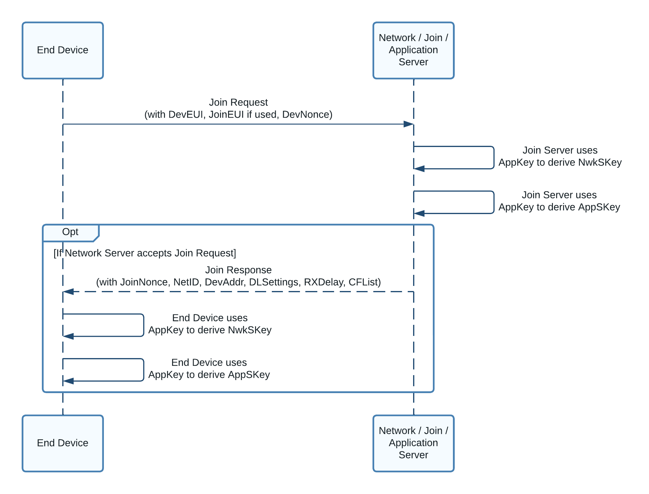
Figure 7: Sequence diagram showing the data transferred and keys generated during the Join Procedure
Step 3A: End Device Sends Join Request
To initiate the join procedure, the end device issues a join request frame containing the JoinEUI, DevEUI, and a DevNonce as shown in figure 8.
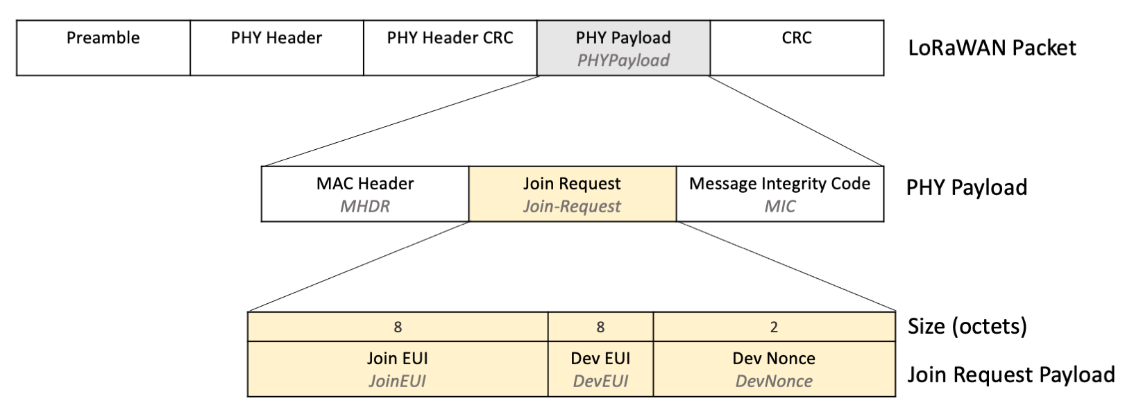
Figure 8: Join Request payload shown within the PHY Payload in the LoRaWAN Packet
Join Request Payload Fields
The JoinEUI and DevEUI are stored on the device as explained in section Step 1: Provision End Device with Keys. The code handling the join request retrieves these keys from the device.
The DevNonce is a counter that should start from 0 and must be incremented with every single join request that is sent to the network server. The DevNonce should never be reused. If no join accept message is received, and the same join request is repeated, then the DevNonce must still be incremented.
Warning
The network server should reject a request that is sent using a previously used DevNonce, so store the DevNonce in non-volatile memory (NVM) that persists between power cycles. If the DevNonce is reset to 0 after a power cycle, and the network server is conforming to the LoRaWAN 1.0.4 specification, the device will be unable to rejoin that network because the DevNonce has not been incremented.
Calculating the Message Integrity Code (MIC)
Calculate the message integrity code (MIC) over the Mac Header (MHDR), JoinEUI, DevEUI, and DevNonce using the AppKey following the instructions in section 6.2.5, Join-Request Frame (page 45) of the TS001-1.0.4 LoRaWAN® L2 1.0.4 Specification. The MIC is used by the network server to ensure the message has not been modified in transit.
Join Request Transmission
Multiple transmissions of the join request should be made across all default channels permitted in the region and at a range of data rates permitted in the region to ensure the message reaches a gateway.
Follow the retransmission backoff procedure described in section 7, Retransmissions Backoff (page 49) of the TS001-1.0.4 LoRaWAN® L2 1.0.4 Specification. These guidelines ensure that the transmission timing across multiple end devices is random enough to avoid flooding the network if they all try to join at the same time.
Follow the steps in section 3.7, Avoiding Synchronous Behavior (page 16) of the document TR007 Developing LoRaWAN® Devices to maximize gateway and network capacity by ensuring randomness in transmission timing and channel selection when sending join requests.
If you operate in a region with a fixed channel plan, read more about use of channels in section 3.2, Fixed Channel Plan Join Process Optimization (page 12) of the document TR007 Developing LoRaWAN® Devices.
Further guidelines on transmission duty cycles, the channels you should use, and the data rates you should use differ between regions. To find the guidelines for your region, open RP002-1.0.3 LoRaWAN Regional Parameters specification, locating the section for the region your device will operate in. The guidelines on Join Requests are found in the subsection entitled REGION NAME Band Channel Frequencies. For example, for the region EU863-870, the section title is EU863-870 Band Channel Frequencies on page 25.
Note
Remember to increment the DevNonce value with every transmission of the join request.
Step 3B: Join Server Handles Join Request
If a separate join server is used, the network server passes the join request to that join server to handle the request. If a separate join server is not used, the network server’s own join server component handles the request.
The join server uses the AES 128-bit encryption algorithm to calculate the NwkSKey and the AppSKey. For both keys, the encryption key used is the AppKey which was provided in step 2 (Provision Network Server and Join Server with Keys). The data input to the encryption includes the join request DevNonce, a join server nonce (JoinNonce) generated by the join server, and the server’s network identifier (NetID). When generating the NwkSKey, the server also includes a value of 0x01 to differentiate the key from the AppSKey which uses a value of 0x02.
The NwkSKey is provided to the network server by the join server so that it can be used to sign and verify the integrity of messages and encrypt MAC-only data frames.
The AppSKey is provided to the application server by the join server so that it can be used to encrypt and decrypt application data frames.
In order that the end device can derive the exact same keys as the network server, the JoinNonce and NetID are returned to the end device in the next step, the join accept. There, the end device will derive the same keys, as described below.
Step 3C: Network Server Sends Join Accept
If the join was accepted, the network server prepares a join accept frame containing the fields required to generate the NwkSKey and AppSKey, the join server nonce (JoinNonce), and the join server network identifier (NetID). Additional fields are supplied by the network server and added to the join accept: the end device address (DevAddr), the downlink configuration settings (DLSettings), a desired delay between transmission and opening receive windows (RXDelay), and an optional list of network parameters (CFList). In the next step we describe what the end device should do with each field.
The MIC is calculated using the AppKey over the Mac Header (MHDR) and all the fields in the join accept frame.
The JoinNonce, NetID, DevAddr, DLSettings, RXDelay, CFList, and MIC are then encrypted using the AppKey as the secret. The output is transmitted as the join accept frame, to be handled as explained in the next step.
Note
The join server encrypts the join accept using the AES decrypt function in Electronic Code Book (ECB) mode. The end device must therefore run the AES encrypt function in ECB mode on join accept, and not the AES decrypt function. This means the end device only requires support for AES encrypt and not AES decrypt. Read more about this in section 6.2.6 Join-Accept frame (page 45) of the TS001-1.0.4 LoRaWAN® L2 1.0.4 Specification.
Warning
If the join was not accepted, then no response is returned to the end device.
Step 3D: End Device Handles Join Accept
If the join server processed the join request successfully, the end device should receive the encrypted join accept response frame.
Decrypt the Encrypted Field
The encrypted field containing all the join accept fields and the MIC is found within the PHY Payload in the LoRaWAN packet as shown in figure 9.
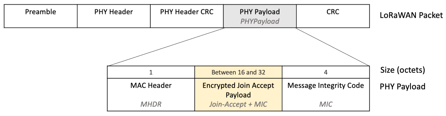
Figure 9: Join-Accept and MIC encrypted, shown within the PHY Payload in the LoRaWAN Packet
Note
The exact size of the encrypted payload depends on whether there were any network parameters (CFList) supplied in the join accept. Since the MHDR length is fixed at 1 octet, and the MIC length is fixed at 4 octets, you decrypt all the remaining octets between the first octet and the final 4 octets.
Decrypt the octets containing the encrypted payload using the AES encrypt function in Electronic Code Book (ECB) mode, with the AppKey as the secret.
Warning
The encrypted join accept frame is decrypted using the AES encrypt function in ECB mode, and not AES decrypt. This is to avoid the end device having to implement both AES encryption and decryption.
The fields returned after decryption, as shown in figure 10, are the join server nonce (JoinNonce), join server network identifier (NetID), end device address (DevAddr), the downlink configuration settings (DLSettings), a desired delay between transmission and opening receive windows (RXDelay), and the optional list of network parameters (CFList), as well as a repeat of the message integrity code (MIC), also found in the PHYPayload.
Figure 10: Fields found after decrypting the encrypted payload
Note
When dividing the decrypted output into individual fields, note that the fields up to the CFList are all fixed in length (12 octets total), and the MIC after the CFList is fixed in length (4 octets). This means the remaining octets, if any are left over, comprise the optional CFList field.
Verify the Message Integrity Code (MIC)
Calculate the message integrity code (MIC) to verify the integrity of the join accept message and ensure it has not been tampered with. Calculate the MIC over the Mac Header (MHDR), JoinNonce, NetId, DevAddr, DLSettings, RXDelay, and CFList using the AppKey following the instructions at line 1481 in section 6.2.6, Join-Accept frame (page 45) of the TS001-1.0.4 LoRaWAN® L2 1.0.4 Specification.
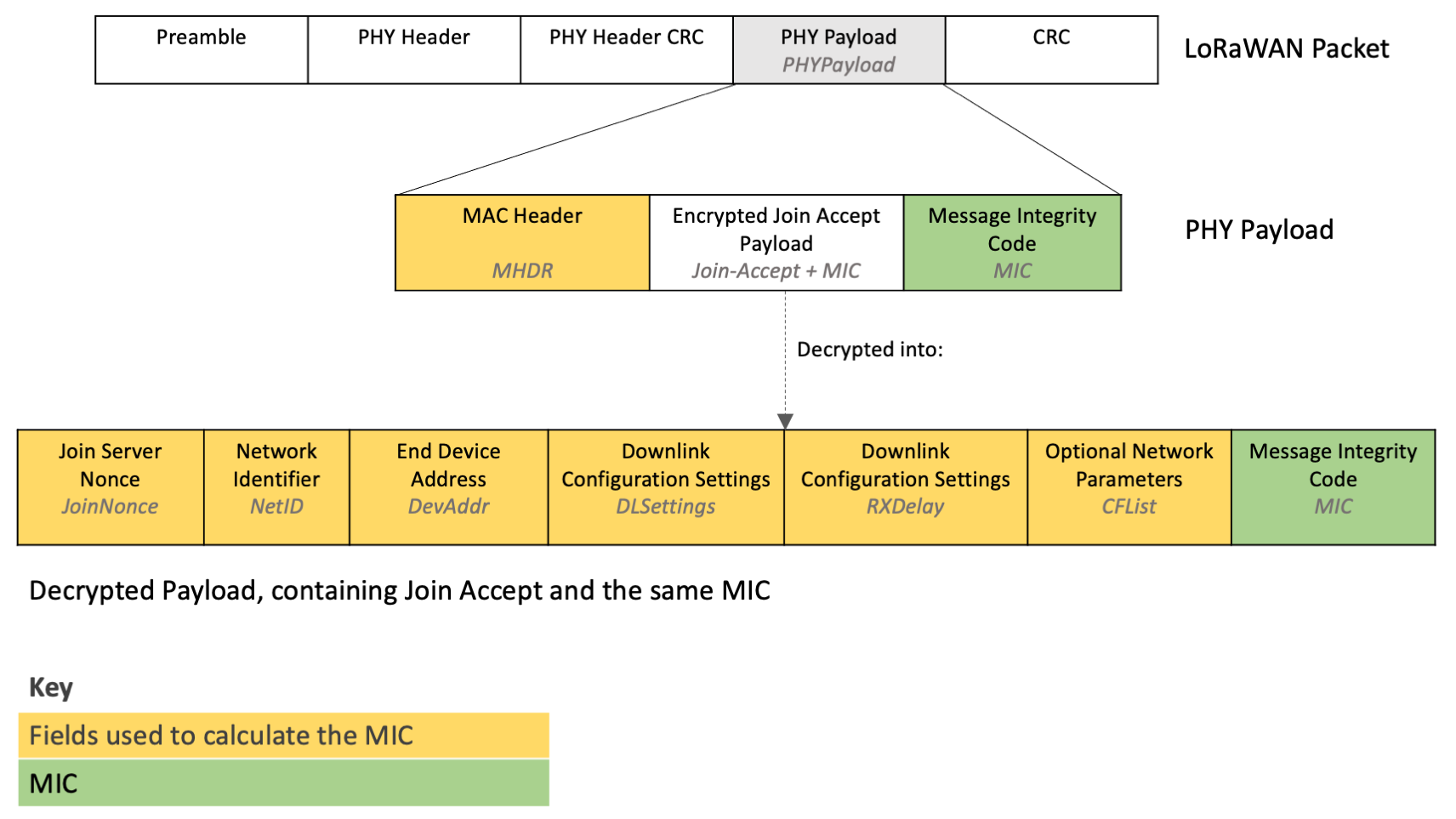
Figure 11: Fields used to calculate the MIC
Verify that the MIC you calculate matches the MIC returned in the PHY Payload, as well as the MIC found in the encrypted payload that was just decrypted. If any MIC does not match the others, ignore this message.
Check the Join Nonce to Prevent Join Accept Replay Attacks
An adversary located within range of the end device can record a join accept message, and then replay that message in response to a future join request issued by the device. If the end device accepts this replayed join accept, it will generate the session keys using the JoinNonce in the older join accept, which will be different from the JoinNonce used by the network server. As a result, the end device will generate incorrect session keys, and the network server will reject any further uplinks. This type of attack is described in more detail in the section entitled Issue #1: Join-accept replays (page 6) of the technical recommendation document Technical Recommendations for Preventing State Synchronization Issues around LoRaWAN® 1.0.x Join Procedure.
To help prevent the join accept replay attack, the end device could store every single JoinNonce ever received in a join accept, rejecting the new join accept if it contains a JoinNonce that is on the stored list. The Join Nonces must be stored in non-volatile memory (NVM) so that they are not lost when the device is power cycled. However, storing every single Join Nonce would consume a lot of memory over time. Therefore, as a minimum, the device should store a reasonable number of previous Join Nonces. This will prevent a join accept replay attack based on a join accept sent within a reasonable time frame prior to the attack.
The section entitled Remedy #1: Preventing Join-accept replays (page 8) of the technical recommendation document Technical Recommendations for Preventing State Synchronization Issues around LoRaWAN® 1.0.x Join Procedure recommends join servers use a device-specific incrementing counter as the JoinNonce, which increments once for each join accept issued. This means the JoinNonce received for each join accept would be 1, then 2, then 3 etc. Your end device then checks that the JoinNonce in the join accept is higher than the previously stored JoinNonce, ignoring the entire join accept if it is not. If the join accept is accepted, the new JoinNonce is stored in NVM. When implementing this check, you must be certain that the network server or join server you use supports an incrementing JoinNonce. Check the documentation at the join server/network server or contact your provider. The end device implementing this check can no longer be moved to a network server or join server that does not implement an incrementing JoinNonce. To ensure that your end device can be moved between network servers/join servers and remain as secure as possible, you could have the software on the end device enable or disable the incrementing JoinNonce behavior via a downlink.
Warning
Incremental JoinNonce validation checks mean that when the device is moved between networks, the join accept will be rejected, even if the new network server/join server also uses an incremental JoinNonce. Some network servers allow you to define the value of the first JoinNonce. In case a network server/join server does not support the ability to set the initial JoinNonce, you will need to program an option that allows you to reset the last stored JoinNonce on the device via a downlink or using a hard-wired connection.
Generate the Session Keys
You use the same algorithm as the join server used to generate the NwkSKey and AppSKey session keys. The keys are generated using the AppKey along with the JoinNonce, NetID, and DevNonce found in the decrypted join accept payload. Follow the instructions at lines 1479 and 1480 in section 6.2.6, Join-Accept frame (page 45) of the TS001-1.0.4 LoRaWAN® L2 1.0.4 Specification to generate the keys.
Note
Store the NwkSKey and AppSKey session keys in non-volatile memory (NVM) to avoid having to rejoin the network when the device is power cycled.
Store the Device Address (DevAddr)
The device address (DevAddr) found in the join accept is used in uplink frames sent from the end device after the activation process. Store the DevAddr in non-volatile memory (NVM) ready for use when sending uplinks.
Handle the Downlink Configuration Settings (DLSettings and RXDelay)
The downlink configuration settings field (DLSettings) contains two settings fields, the RX1DROffset and RX2DataRate fields.
-
RX1DROffset is used by the network server to adjust the data rate offset between the uplink and the first receive window (RX1).
-
RX2DataRate is used by the network server to adjust the data rate for the second receive window following an uplink (RX2).
Following the RX1DROffset and RX2DataRate initially configured in this join accept, these fields are updated via the Receive Windows Parameters MAC Command (RXParamSetupReq). The documentation for this command also serves as a detailed guide to these fields, found in section 5.4, Receive Windows Parameters (page 33) of the TS001-1.0.4 LoRaWAN® L2 1.0.4 Specification.
The RXDelay field defines the delay between the end of the uplink transmission and the opening of the first receive window.
Following the RXDelay initially configured in the join accept, the value is updated via the Receive Window Timing MAC Command (RXTimingSetupReq) Del field. Both fields follow the same conventions. To understand the RXDelay field, read the documentation for the identically formatted Del field in section 5.7, Setting Delay between TX and RX (page 39) of the TS001-1.0.4 LoRaWAN® L2 1.0.4 Specification.
The data rate offset, data rate, and delay communicated by these fields should be used in all further transmissions until informed otherwise by the corresponding MAC commands (RXParamSetupReq and RXTimingSetupReq) and should replace the default regional settings for these values.
Set Initial Data Rate
Set the initial data rate used for transmitting uplinks to the same data rate that was used for the transmission of the join request message that resulted in this join accept being received.
After sending the first uplink, the device should then implement adaptive data rate control as described in Implementing Adaptive Data Rate.
Set MAC Layer Defaults
After setting the values communicated by the RX1DROffset, RX2DataRate, and RXDelay fields and the initial data rate, the end device should now set all remaining MAC layer parameters to the regional default settings including transmit power, number of retransmissions, and channel configurations, also referenced in the section Default Uplink Settings Before Using ADR of our Implementing Adaptive Data Rate paper.
Network Parameters (CFList)
A list of network parameters may be supplied in the CFList field. This field may indicate the channels that your end device should be using. The details of these parameters and whether they will be supplied is region-specific. To find the details for your region, open RP002-1.0.3 LoRaWAN Regional Parameters specification, locating the section for the region your device will operate in. The guidelines are found in the subsection entitled REGION NAME Join-Accept CFList. For example, for the region EU863-870, the section title is EU863-870 Join-Accept CFList on page 27.
Reset the Frame Counters (FCntUp and FCntDown)
Reset the frame counters (FCntUp and FCntDown) values to 0.
The first uplink sent by the end device after activation includes FCntUp set to 0. FCntUp is incremented by 1 for all subsequent new uplink messages.
When each new downlink is received from the network server the FCntDown is incremented. If the new downlink contains an FCntDown that is lower than the FCntDown in the previous received message, the downlink is ignored.
Learn more about the frame counter in section 4.3.1.5, Frame Counter (page 22) of the TS001-1.0.4 LoRaWAN® L2 1.0.4 Specification.
Note
The frame counters do not need to be stored in non-volatile memory (NVM) unless power cycling your device does not trigger a rejoin. Typically, a power cycle will cause the device to rejoin the network server, which must reset the frame counters.
Step 4: End Device Sends First Uplink
The end device can now send the first uplink using the new session keys, with FCntUp set to its new value of 0.
It is recommended that the very first message sent contains information about the device, including the firmware revision. Read more advice about the first uplink in our paper Developing LoRaWAN-based Devices: Things to know, Firmware Version and Status Advertising in Frame 0.
Encrypt data frames containing a MAC-only payload using the NwkSKey as described in section Use of the NwkSKey for Encryption of MAC-Only Data Frames.
Encrypt data frames containing an application-specific payload using the AppSKey as described in Use of the AppSKey for Encryption of Application-Specific Data Frames.
Calculate the MIC using the NwkSKey as described in section Use of the NwkSKey for Integrity Verification.
Learn more about sending uplinks in section 4, MAC Frame Formats (page 15) of the TS001-1.0.4 LoRaWAN® L2 1.0.4 Specification.
Completing the Join Procedure for Class C Devices
If your end device uses Class C, whereby a downlink can be received by the end device at any time except when transmitting, the network server will not begin sending downlinks until it first receives an uplink from the end device.
You should immediately send a message that requires a server acknowledgement - a confirmed uplink, for example. Continue to send this message, respecting duty cycle and retransmission guidelines, until the corresponding downlink is received from the network server.
If the end device has sent the message the number of times defined by the variable ADR_ACK_LIMIT and still not received a response, begin the process of joining again by sending another join request. The value for ADR_ACK_LIMIT is defined in the Regional Parameters document in the section Default Settings. In version RP002-1.0.3, ADR_ACK_LIMIT is set to 64.
Read more about completing the join procedure for Class C devices in the section entitled Remedy #3: Rapid key confirmation (page 9) of the technical recommendation document Technical Recommendations for Preventing State Synchronization Issues around LoRaWAN® 1.0.x Join Procedure.
Rejoining the Network
To avoid accidentally becoming disconnected from the network, you should implement a strategy to ensure the device remains connected. Read about some recommended strategies in our paper Developing LoRaWAN-based Devices: Things to know, Joining and Rejoining.
Activation By Personalization (ABP)
The session keys (NwkSKey and AppSKey), DevAddr, and DevEUI are all stored in non-volatile memory (NVM) on the end device during the manufacturing process.
Set the FCntUp value to 0, and store this in NVM to ensure that the frame counter value is never reset, which would lead to uplinks being rejected by the network server.
There is no further join procedure. These fields cannot be changed once the device has been created unless the device is reprogrammed.
If possible, allow support for OTAA activation in ABP devices by provisioning them with a DevEUI, JoinEUI, and AppKey, as well as ensuring that they can handle the OTAA process described above. This allows the device to operate as an OTAA device later. The ability to activate OTAA could be programmed to be activated by a downlink, or from a hard-wired cable.
Provision End Device with Keys
Device EUI (DevEUI)
The LoRaWAN 1.0.4 specification introduced the requirement for ABP devices to be provisioned with a DevEUI as well as NwkSKey, AppSKey, and DevAddr. Follow the instructions in the section Device EUI (DevEUI) to learn how to obtain a DevEUI.
Device Address (DevAddr)
If your device will be registered with a public network, the DevAddr must be supplied by the network server. If the network server is private, you can generate your own DevAddr by following the guidelines in section 6.1.1 End-device address (page 42) of the TS001-1.0.4 LoRaWAN® L2 1.0.4 Specification. Further advice on obtaining a DevAddr is found in Developing LoRaWAN-based Devices: Things to know, Device Address and Activation by Personalization.
Warning
An ABP device on a public network must use the DevAddr supplied by the network server. This means that the device will be tied to that network and cannot be moved to another network. Support OTAA activation as well, to enable the device to be moved to another network later.
Session Keys (NwkSKey and AppSKey)
The NwkSKey and AppSKey session keys are types of root key. Read section 2.5.3, Root Keys (page 9) of TR007 Developing LoRaWAN® Devices V1.0.0 to learn how to securely generate and store root keys.
Warning
A good practice is to print the DevEUI on the cover of the end device to ease device management. Never include the session keys NwkSKey or AppSKey on the cover of the end device.
Frame Counters (FCntUp and FCntDown)
Set FCntUp and FCntDown to 0, storing them in non-volatile memory (NVM) to ensure the persist when the device is power cycled.
The first uplink sent by the end device should have FCntUp set to 0. FCntUp is incremented by 1 for each subsequent new uplink message.
When each new downlink is received from the network server, the FCntDown is incremented. If the new downlink contains an FCntDown that is lower than the FCntDown in the previous received message, the downlink is ignored.
Learn more about the frame counter in section 4.3.1.5, Frame Counter (page 22) of the TS001-1.0.4 LoRaWAN® L2 1.0.4 Specification.
Warning
If you do not store FCntUp and FCntDown in NVM, when the device is power cycled the FCntUp will be reset to 0, and the network server will reject the uplink since the FCntUp will be lower than the previous. The device will become disconnected. To resolve this, you may be able to modify the settings for the end device in your network server if supported, or you will have to remove and then re-add the device on the network server.
End Device Activation Best Practices
Key best practices referenced in this document are listed here for your reference:
-
Do not implement ABP, but if you must, also support OTAA.
-
Use the DevEUI supplied by the radio module manufacturer or obtain a valid, globally unique DevEUI that you own.
-
If you use a separate join server, you must use the JoinEUI provided by that join server; otherwise, use a single EUI that you own as the JoinEUI for all your devices.
-
Generate the AppKey by following advice on secure root key generation.
-
Select an approach to prevent the join accept relay attack, as described in Check the Join Nonce to Prevent Join Accept Replay Attacks.
-
Print a QR code to attach to the end device containing the DevEUI and JoinEUI. Never include the AppKey (for OTAA) or NwkSKey / AppSKey (for ABP) in this QR code.
-
To ensure that a power cycle does not require the device to rejoin, store the AppSKey, NwkSKey, last used DevNonce, and any JoinNonce values in non-volatile memory (NVM). If you use ABP, the FCntUp should also be stored in NVM.
Conclusion
In this paper we have explained end device activation for end device manufacturers implementing LoRaWAN Link Layer Specification 1.0.4. You should now understand the differences between ABP and OTAA, and how to implement each to the specification. You should also now have a good understanding of end device activation best practices, ensuring that your devices remain secure, and how to efficiently join a network.
Further Reading
Read these technical specifications for a full understanding of LoRaWAN 1.0.4 and related concepts:
Read these formal technical recommendations for an overview of best practices:
Read our papers on other LoRaWAN 1.0.4 concepts:
To view an example of how end device activation is implemented within the LoRa MAC layer implementation for LoRaWAN Link Layer specification 1.0.4 in C, download the LoRaMAC-Node end device stack implementation. Read our LoRaMAC-Node Hands-on Lab to learn how to use the LoRaMAC-Node reference implementation.