documentation
In-Depth: Sending and Receiving Messages with LoRaWAN®
This paper covers sending and receiving messages for end devices implementing LoRaWAN® 1.0.4 in depth. It is aimed at end device software developers and managers of teams building devices with LoRa® that implement the LoRaWAN Link Layer Specification v1.0.4. This paper helps you gain an understanding of each field used in different types of messages as well as fundamentals and best practices on the radio settings and timings to use when transmitting and receiving messages.
Already using software to handle the network layer of LoRaWAN such as LoRaMAC-Node™? This article gives you the background you need to fully understand what the software is doing and make informed decisions about what to use and when, which settings to choose, and how to ensure that you are following best practices.
Sending Messages (Uplinks) and Opening Receive Windows
Messages sent from an end device to a network server via one or more nearby gateways are referred to as uplinks.
In this section, you learn the rules and best practices to follow when sending uplinks from your end device using the LoRaWAN® 1.0.4 specification.
Types of Uplinks
Uplink messages may include one or both of the following types of information:
-
Application data used to transmit readings and other information from the end device. This type of data is specific to the use case your end device implements. Examples include temperature readings from a sensor, or a message to confirm that a valve has been closed.
-
MAC commands and MAC command acknowledgements used for LoRaWAN network administration. Find details of each MAC command the end device can initiate in our LoRaWAN MAC Commands paper.
An uplink message also contains bit fields (which are always sent, set to either on or off), that send the following information:
-
Confirmation of receipt of a confirmed downlink message received from the network server. Confirmed downlinks are a type of downlink that requires a response from the end device.
-
Additional fields used in adaptive data rate (ADR) and Class B operations.
It is possible for a message to carry neither application data nor MAC commands. Examples include when the end device sends an empty uplink for the sole purpose of receiving a downlink, responding to a confirmed downlink without accompanying data, and informing the network server it is moving to Class B mode.
Composing the Packet
An uplink message is sent in a LoRaWAN uplink packet. The LoRaWAN packet shown in figure 1 contains a PHY Payload (PHYPayload) which contains three groups of fields:
-
a MAC Header (MHDR) defining information about the type of message and its format version
-
a MAC Payload (MACPayload) containing the information being transmitted
-
a Message Integrity Code (MIC) used by the network server to verify that the message originated from the same end device registered with the network server
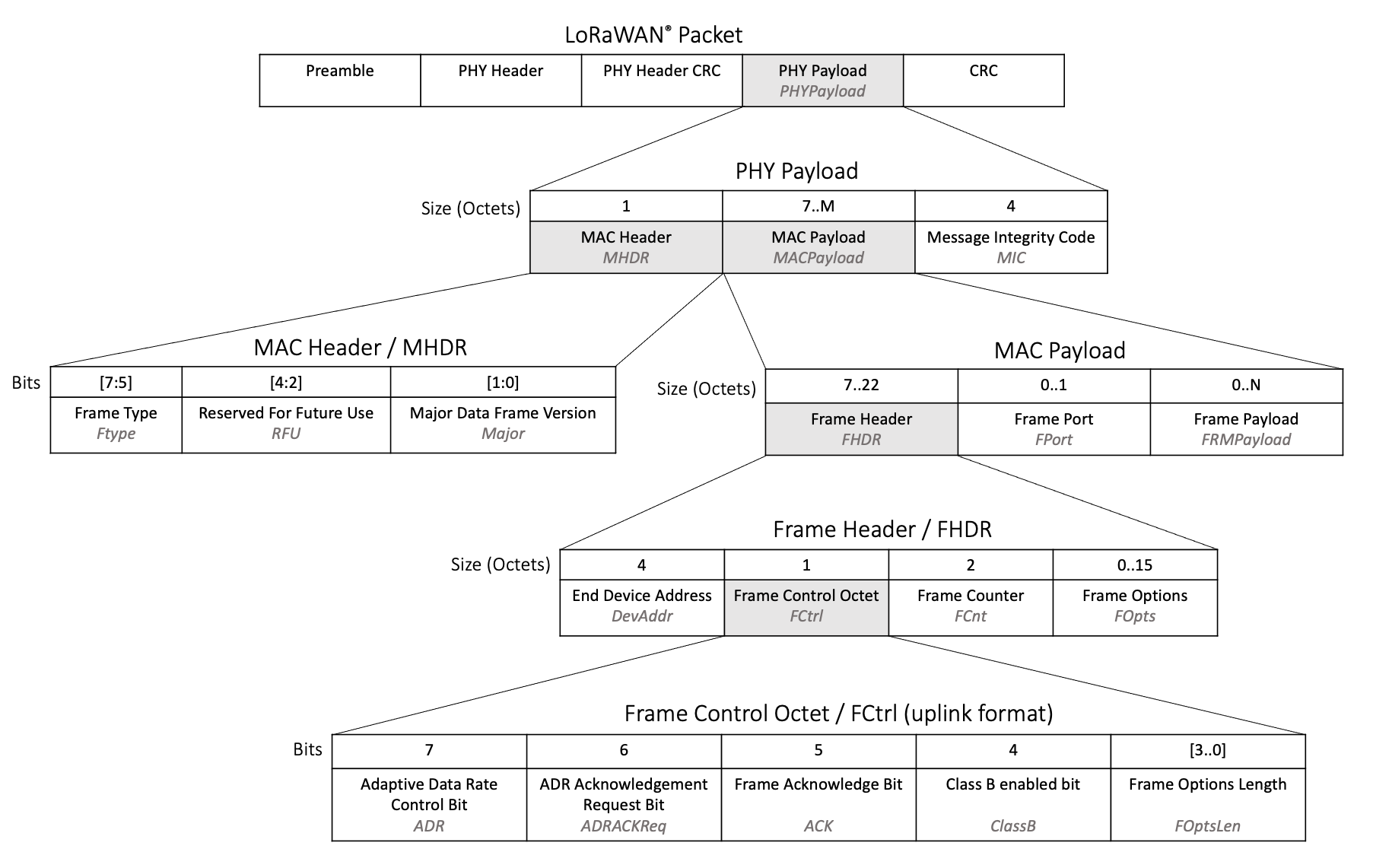
Figure 1: Fields contained in a LoRaWAN uplink packet
The section below explains how the end device should set each field in the MAC Header and MAC Payload. Understanding how to set the Message Integrity Code is then explained in the section Calculating the Message Integrity Code.
Metadata Fields
These fields, highlighted in figure 2, must all be sent within each uplink.
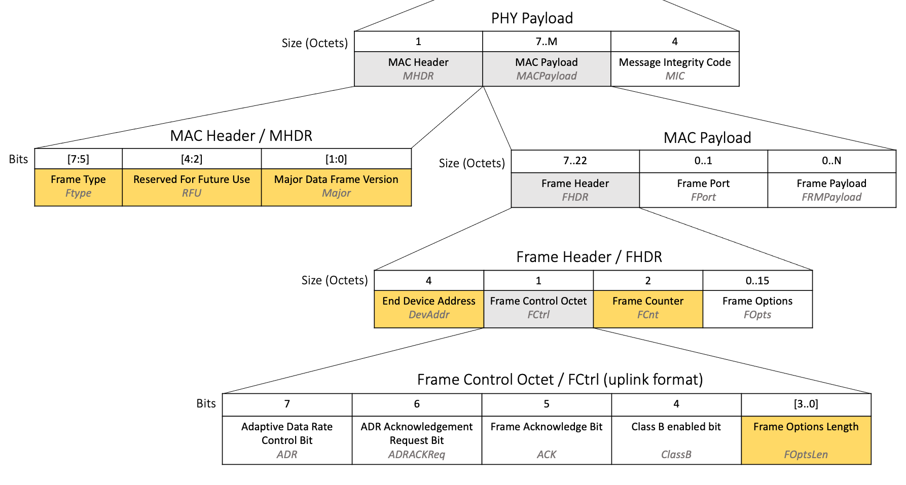
Figure 2: Metadata fields highlighted in a LoRaWAN uplink packet
- Frame Type (FType)
-
The FType field is three bits long at position [7:5] inside the MAC Header as shown in figure 2.
FType is used to identify that the frame is an uplink and whether a response is required from the network server.
Set to 010 (unconfirmed data uplink) if the end device does not require a response from the network server. Sending an unconfirmed data uplink uses less power and network time, so use this unless you have a good reason.
Set to 011 (confirmed data uplink) if the end device requires a response from the network server. When the end device sends a confirmed uplink, the response will come in one of the two receive windows opened directly after the transmission of this message. Learn how to handle the response in the section Processing the Downlink Packet.
Read more in section 4.2.1, Frame types (page 16) of the TS001-1.0.4 LoRaWAN® L2 1.0.4 Specification.
- MHDR Reserved for future use (RFU) Field
-
The MAC Header RFU field is three bits long at position [4:2] inside the MAC Header as shown in figure 2.
RFU is reserved for future use, and has never been in use as of LoRaWAN 1.0.4.
Set the MHDR RFU to 000.
- Major Data Frame Version (Major)
-
The Major field is two bits long at position [1:0] inside the MAC Header as shown in figure 2.
Major defines the major version of the frame format used to construct the packet being sent alongside it.
Set Major to 00, which is the current major version of the frame format.
Read more in section 4.2.2, Major data frame version (page 17) of the TS001-1.0.4 LoRaWAN® L2 1.0.4 Specification.
- End Device Address (DevAddr)
-
The DevAddr field is four octets long and is positioned inside the Frame Header within the MAC Payload as shown in figure 2.
DevAddr is used by the network server to identify the end device.
Set the DevAddr field to the same DevAddr value which was set during the end device activation process (described in the Data Stored in End Device After Activation section of our In-Depth: LoRaWAN® End Device Activation paper).
Read more about the DevAddr in section 6.1.1, End-device address (page 42) of the TS001-1.0.4 LoRaWAN® L2 1.0.4 Specification.
- Frame Counter (FCnt)
-
The FCnt field is two octets long and is positioned inside the Frame Header within the MAC Payload as shown in figure 2.
FCnt is used to send the current uplink frame counter (referred to in the specification as FCntUp) to the network server. The frame counter is used by the network server to ensure it has not already received the message.
The end device must store a value entitled FCntUp in memory. Set FCntUp to 0 when the device first joins the network or is provisioned for activation by personalization (ABP). When a new uplink message is about to be sent from the end device to the network server, the value of FCntUp must be incremented by 1. When retransmitting the same uplink message, the value of FCntUp must not be incremented. Following these rules, the FCnt field can then be set to the current FCntUp value stored in memory.
Read more in section 4.3.1.5, Frame counter (page 22) of the TS001-1.0.4 LoRaWAN® L2 1.0.4 Specification.
- Frame Options Length (FOptsLen)
-
The FOptsLen field is four bits long at position [3..0] inside the Frame Control octet within the Frame Header as shown in figure 2.
If the uplink will contain both MAC commands and application data, then the MAC commands must be sent in the FOpts field. The FOpts field can be between 0 and 15 octets long. This FOptsLen field identifies how many octets the variable length FOpts field contains.
For example, if the FOpts field is 4 octets long, then the FOptsLen field should be set to 4. If the FOpts field is not in use, FOptsLen should be set to 0.
Read more in section 4.3.1.6, Frame options (page 23) of the TS001-1.0.4 LoRaWAN® L2 1.0.4 Specification.
Fields Used When Sending Application Data and MAC Commands
The fields described in this section are used when sending a message that contains application data or MAC commands.
When sending MAC commands on their own or application data on its own, the Frame Port and Frame Payload fields are used to define the data type and send the application data respectively.
When sending both application data and MAC commands, the Frame Options field is used to carry the MAC commands, with the Frame Port and Frame Payload fields used to define the data type and send the application data respectively.
When sending neither application data nor MAC commands, the Frame Options, Frame Port, and Frame Payload fields are not set.
View some examples of different combinations of application data and MAC commands in the section Appendix: Illustrative Examples of Combinations of Data Types in Messages.
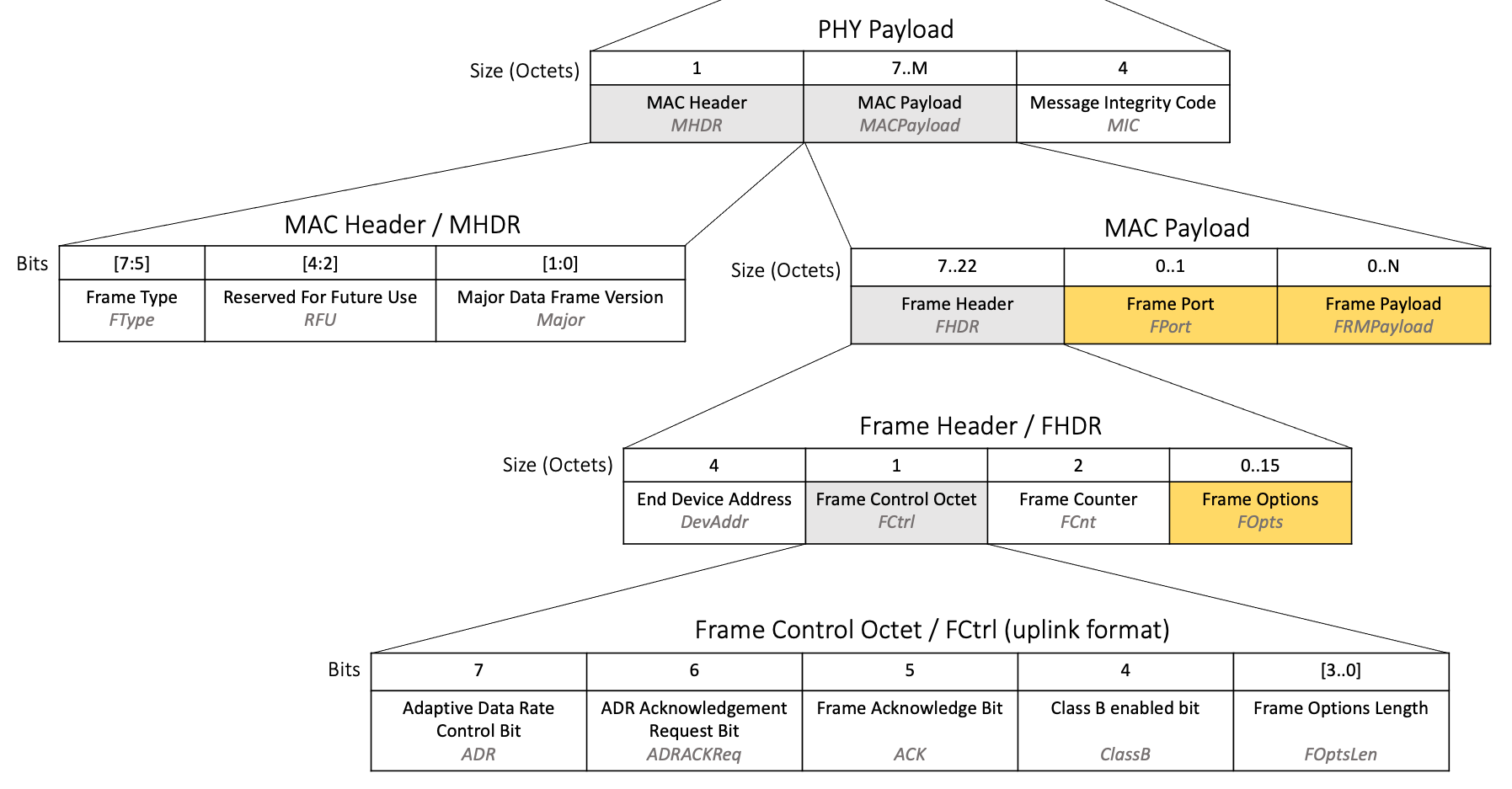
Figure 3: Application data and MAC command fields highlighted in a LoRaWAN uplink packet
- Frame Port (FPort)
-
FPort is an optional field of variable length between zero and one octet, located within the MAC Payload as shown in figure 3.
FPort is used to define the type of message contained in the Frame Payload (FRMPayload) field.
If the uplink packet is transmitting MAC Commands in the FRMPayload field, set FPort to 0.
If the uplink packet is transmitting application data in the FRMPayload, set FPort to any value between 1 and 223.
Note
The application data FPort value can be used to help your users identify the type of data being transmitted. For example, if the end device broadcasts both temperature and humidity in separate messages, FPort could be set to 1 to identify a message containing temperature, and set to 2 to identify a message containing humidity. This allows messages in the FRMPayload field to be as short as possible, as there is no need to add any identifying characters at the front of the message.
If the uplink packet is not transmitting any data and is transporting an empty message or a confirmed downlink acknowledgement only, do not supply the FPort field, leaving it empty with the length of the field at zero octets.
Read more in section 4.3.2, Port field (page 23) of the TS001-1.0.4 LoRaWAN® L2 1.0.4 Specification.
- Frame Payload (FRMPayload)
-
FRMPayload is an optional field of variable length between zero and N octets, located within the MAC Payload as shown in figure 3. The value of N depends on the region the end device will operate in and the data rate it will use to transmit the data. Learn more in the Packet Size Considerations section of our Developing LoRaWAN®-based Devices book.
FRMPayload is used to transport MAC commands or application-specific data.
If the uplink is sending MAC commands in the FRMPayload field, FPort must be set to 0. The commands must be encrypted using the network session key (NwkSKey) before setting them in the FRMPayload field. Learn more about obtaining the NwkSKey in our paper In-Depth: LoRaWAN® End Device Activation. Find the encryption algorithm to use in section 4.3.3, MAC frame payload encryption (page 24) of the TS001-1.0.4 LoRaWAN® L2 1.0.4 Specification. Guidance on the MAC commands that can be sent and the format used to represent them can be found in the MAC Commands Initiated by the End Device section of our paper A Deep Dive into LoRaWAN® MAC Commands.
If the uplink is sending application data in the FRMPayload field, FPort must be set to a value between 1 and 223.
The raw application data needs to be transformed into a compact format before transmission. The message could be encoded using the Cayenne Low Power Payload standard, which has the benefit of being supported by some network servers, enabling users to identify a device as using a Cayenne LPP encoder and not having to include a decoder themselves. This eliminates the need for you to publish a decoder and reduces the amount of documentation and decisions you need to make. Alternatively, you can come up with your own encoder specific to this application. Read the Packet Optimization section of our Developing LoRaWAN-based Devices book for advice on designing sufficiently detailed application data packets while respecting packet size limitations.
Once the application data has been encoded, it must then be encrypted using the application session key (AppSKey) before setting it in the FRMPayload field. Learn more about obtaining the AppSKey in our paper In-Depth: LoRaWAN® End Device Activation. Find the encryption algorithm to use in section 4.3.3, MAC frame payload encryption (page 24) of the TS001-1.0.4 LoRaWAN® L2 1.0.4 Specification.
If the uplink is not transmitting any data and is broadcasting an empty message or a confirmed downlink acknowledgement only, do not supply the FRMPayload field; instead, leave it empty so the length of the field is zero octets. The FPort field must also be left empty in this case.
- Frame Options (FOpts)
-
FOpts is an optional field of variable length between zero and fifteen octets, located within the Frame Header inside the MAC Payload as shown in figure 3.
The FOpts field is used to transmit MAC commands in the same packet as application-specific data (referred to as piggybacking). Up to 15 octets of MAC commands can be sent in the FOpts field. The FOptsLen field must also be set to the length of the FOpts field as described in the section Metadata Fields. Learn more about MAC commands in our paper A Deep Dive into LoRaWAN® MAC Commands.
Warning
If the uplink is transporting MAC commands on their own, without any application data in the same packet, it must use the FRMPayload field to transmit them instead of the FOpts field.
When the FOpts field is being used to transport MAC commands, the FPort field must not be set to 0.
Read more in section 4.3.1.6, Frame options (page 23) of the TS001-1.0.4 LoRaWAN® L2 1.0.4 Specification.
Uplink Bit Fields
The following one-bit-length fields must always be set to 1 or 0 and sent with every uplink broadcast. The end device can also send a message purely for the purpose of communicating one or more of these bit fields, without any application data or MAC commands, if the use case requires it.
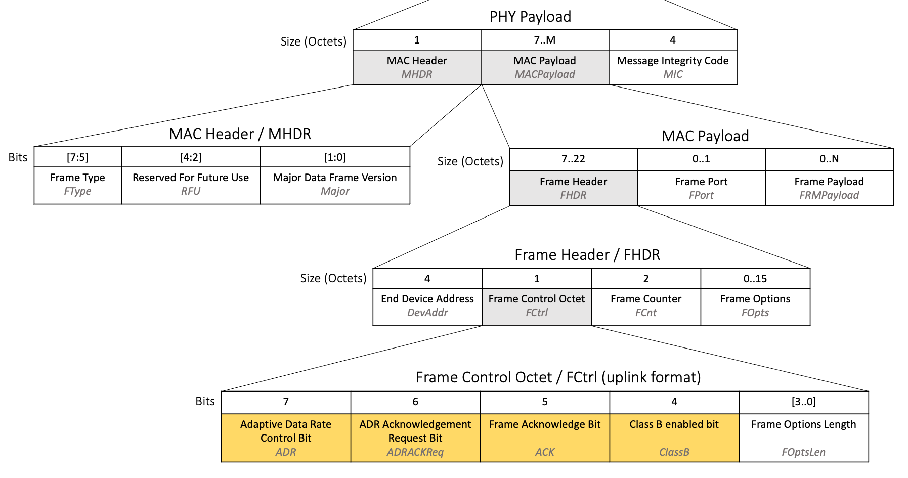
Figure 4: The bit fields highlighted in a LoRaWAN uplink packet
- Frame Acknowledge Bit (ACK)
-
The ACK bit is found at position 5 in the Frame Control Octet found within the Frame Header inside the MAC Payload, as shown in figure 4.
The ACK bit is used to acknowledge receipt of a confirmed downlink, described in the section Processing the Downlink Packet.
Set the ACK bit to 1 to confirm receipt of the last received confirmed downlink; otherwise, set ACK to 0.
You will need to decide if you should program your device to wait for the next MAC command or application data broadcast to pass up the Frame Acknowledge Bit, or to send the Frame Acknowledge Bit as soon as it is ready. Waiting to send the field until there is other data to send consumes less overall airtime and battery life, as the device will send fewer messages overall. However, there are certain cases when it may be necessary to send the bit as soon as possible, depending on your use case.
Read more in section 4.3.1.2, Frame acknowledge bit and acknowledgment procedure (page 20) of the TS001-1.0.4 LoRaWAN® L2 1.0.4 Specification.
- Adaptive Data Rate Control Bit (ADR)
-
The ADR bit is found at position 7 in the Frame Control Octet found within the Frame Header inside the MAC Payload, as shown in figure 4.
The ADR bit is used by the adaptive data rate (ADR) feature. The ADR bit is set to inform the network server that the end device is ready to allow the network server to use ADR to manage its settings. Set this when first starting to implement ADR, and with each message thereafter until the end device stops implementing ADR. Learn more about ADR in our paper Implementing Adaptive Data Rate (ADR).
Set ADR to 1 to inform the network server that ADR should be used. It is recommended to always use and implement ADR as long as the device is intended to remain in a stationary position. Mobile trackers and other devices that move around should use ADR when and only when they are stationary.
Read more in section 4.3.1.1, Adaptive data-rate control in frame header (page 18) of the TS001-1.0.4 LoRaWAN® L2 1.0.4 Specification.
- Adaptive Data Rate Acknowledgement Request Bit (ADRACKReq)
-
The ADRACKReq bit is found at position 6 in the Frame Control Octet found within the Frame Header inside the MAC Payload, as shown in figure 4.
The ADRACKReq bit is used by the adaptive data rate (ADR) feature. The ADRACKReq bit is set when the end device requires a downlink frame to be sent by the network server in response to the message. Learn more about ADR in our paper Implementing Adaptive Data Rate (ADR).
Set ADRACKReq to 1 to request a downlink frame; otherwise, set ADRACKReq to 0.
Read more in section 4.3.1.1, Adaptive data-rate control in frame header (page 18) of the TS001-1.0.4 LoRaWAN® L2 1.0.4 Specification.
- Class B Enabled Bit (ClassB)
-
The ClassB bit is found at position 4 in the Frame Control Octet found within the Frame Header inside the MAC Payload, as shown in figure 4.
The ClassB bit is used to notify the network server that the end device currently has Class B operations enabled.
Set ClassB to 1 when the end device wants to enable and use Class B mode, and with every subsequent message until the end device switches back to Class A mode or moves into Class C mode; otherwise, set ClassB to 0.
Read more in section 4.3.1.7, Class B enabled bit (page 23) of the TS001-1.0.4 LoRaWAN® L2 1.0.4 Specification.
Calculating the Message Integrity Code
After all the data has been prepared in the fields and the FRMPayload field has been encrypted as described in the previous section, the end device application can calculate and then set the Message Integrity Code (MIC). The MIC is calculated over the Mac Header (MHDR), Frame Header (FHDR), Frame Port (FPort), and encrypted Frame Payload (FRMPayload) using the NwkSKey following the instructions at line 801 in section 4.4, Message Integrity Code (page 25) of the TS001-1.0.4 LoRaWAN® L2 1.0.4 Specification. The NWkSKey is obtained during the join procedure explained in In-Depth: LoRaWAN® End Device Activation. Figure 5 highlights the fields that are used in the MIC calculation.
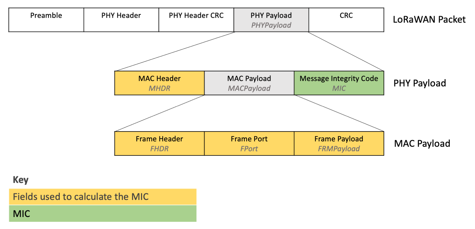
Figure 5: Fields used to calculate the MIC
Timing of the Broadcast
Every application will likely have a range of different pieces of application data that need to be broadcast on different schedules.
Firstly, choose a rough schedule for each item of data that needs transmitting, for example once every 15 mins, once every day, once every 7 days, or similar. Read more about timing in the Heartbeat Messages and Data Packet Transmissions sections of our Developing LoRaWAN-based Devices book.
Once you have a rough schedule in mind, you need to program this schedule into the end device. Do not simply set each message to broadcast at a fixed time, or after a few seconds have elapsed; this can result in all of your end devices broadcasting simultaneously, which will cause network congestion. Instead, use pseudo-random delays when identifying a moment to broadcast, as described in section 3.7 Avoiding Synchronous Behavior (page 16) of TR007 Developing LoRaWAN® Devices V1.0.0.
Note
You might also want to make some of the schedules end-user-configurable using a downlink, as discussed in the section Types of Downlinks.
Channel, Data Rate, and TX Power Guidelines for Broadcasting
This section explains how to work out which channel, data rate, and TX Power should be used for the transmission, which vary based on:
-
the region the device is operating in
-
whether the end device is using the defaults or has received updates from the network server
-
whether the end device is working through the ADR backoff process whereby it attempts to restore lost connectivity
Channel
Find out if the region your device supports is a fixed channel plan region or a dynamic channel plan region by reading section 1.3 Regional Parameters Summary Table in the RP002-1.0.3 LoRaWAN Regional Parameters specification. This table groups the regions into Dynamic and Fixed Channel Plans.
After each end device has been reset, it should generate a pseudo-randomly sorted list of channels and then iterate through each channel in this list with each broadcast, as described in section 3.7 Avoiding Synchronous Behavior (page 16) of the TR007 Developing LoRaWAN® Devices V1.0.0. This minimizes the risk of multiple end devices all broadcasting on the same channel. If the end device is in a fixed channel plan region, this list should contain all the available upstream channels. If the end device is in a dynamic channel plan region, this list should contain all the default channels. Find the channels to use in the Band Channel Frequencies section for the region the end device will operate in of the RP002-1.0.3 LoRaWAN Regional Parameters specification.
The network may request your end device to change the enabled channel list in the following circumstances:
-
When an end device uses over the air activation (OTAA) to join the network, it may receive network parameters in the CFList field in the Join-Accept which may change the channels it should use. The details of these parameters and whether they will be supplied are region-specific. To find the details for a given region, open RP002-1.0.3 LoRaWAN Regional Parameters specification and locate the section for the region your device will operate in. Read more about handling the CFList in section Network Parameters (CFList) of our paper In-Depth: LoRaWAN® End Device Activation.
-
When an end device uses adaptive data rate (ADR), it may receive the LinkADRReq MAC command containing Channel Mask Control (ChMaskCntl) in the Redundancy field and the Channel Mask (ChMask) field that requests an update to the channels that should be used for sending uplinks. If the end device responded with an LinkADRAns confirming it can use those channels, then it should be using the updated values. Learn more about handling the LinkADRReq MAC command in the Handling ADR MAC Commands section of our Implementing Adaptive Data Rate paper.
-
The NewChannelReq MAC command may be sent by the network server at any time to end devices in dynamic channel plan regions to create, modify, or disable channels. If the end device responded with a NewChannelAns confirming it can use those channels, then it should be using the updated values. Read more in the Create / Modify a Channel section of our A Deep Dive into LoRaWAN® MAC Commands paper.
When following the ADR Backoff procedure, the end device will eventually be required to re-enable all of the dynamic channel plan default channels or all of the fixed plan channels.
Whenever the enabled channel list requires updating, either following an update from the network or during the backoff procedure, the end device should update the list to include the specified channels, pseudo-randomly sort the list, and recommence iterating through the channels in the new list with each broadcast.
Data Rate
The initial data rate that is used depends on whether the device was activated using over the air activation (OTAA) or activation by personalization (ABP).
Devices activated using OTAA send the join request over the range of data rates listed in the Band Channel Frequencies section for their region of RP002-1.0.3 LoRaWAN Regional Parameters specification. The initial data rate used for uplinks should then be the data rate that was used on the join request that succeeded and resulted in a join accept being received.
Devices activated using ABP should use the lowest numbered data rate listed in the Data Rate and End-device Output Power encoding section for their region in the RP002-1.0.3 LoRaWAN Regional Parameters specification. This has the highest chance of reaching a gateway.
On the initial broadcast, the end device should enable ADR to allow the network to control the data rate thereafter. When the end device uses adaptive data rate (ADR), it may receive the LinkADRReq MAC command with the DataRate field in the DataRate_TXPower octet that requests an update to the data rate used when sending uplinks. If the end device responded with an LinkADRAns confirming it can use the requested data rate, then it must use this data rate. Learn more about handling the LinkADRReq MAC command in the Handling ADR MAC Commands section of our Implementing Adaptive Data Rate paper.
The ADR Backoff procedure should be followed to allow the device to regain connectivity if the circumstances in the environment change, resulting in the device losing contact with surrounding gateways. This will result in the data rate being reduced back to the lowest numbered data rate over time.
TX Power
Following a reset, the end device should begin broadcasting using the maximum power level it can support and is permitted for the region in which it will operate. Find the guidelines for a given region in the section entitled Data Rate and End-device Output Power encoding for the region in the RP002-1.0.3 LoRaWAN Regional Parameters specification.
On the initial broadcast, unless the device will be in motion (for example a tracker on route to a destination), the end device should enable ADR to allow the network to control the TX Power thereafter. When the end device uses adaptive data rate (ADR), it may receive the LinkADRReq MAC command with the TXPower field in the DataRate_TXPower octet that requests an update to the TX Power used when sending uplinks. If the end device responded with an LinkADRAns confirming it can use the requested TX Power, then it must use this TX Power. Learn more about handling the LinkADRReq MAC command in the Handling ADR MAC Commands section of our Implementing Adaptive Data Rate paper.
The ADR Backoff procedure should be followed to allow the device to regain connectivity if the circumstances in the environment change, resulting in the device losing contact with surrounding gateways. This will result in the TX Power eventually being set back to the maximum power level.
Opening the Downlink Windows
Following all uplinks, even if the end device also supports Class B or Class C operations, the end device must listen for a response from the network server. During this period, no further uplinks may be broadcast, and Class B and Class C listening should be paused. This process of sending an uplink and then listening for a downlink is a Class A feature which all devices are required to implement.
At the end of the uplink transmission, the end device must start two timers, RECEIVE_DELAY1 and RECEIVE_DELAY2, as shown in figure 6 and described below.
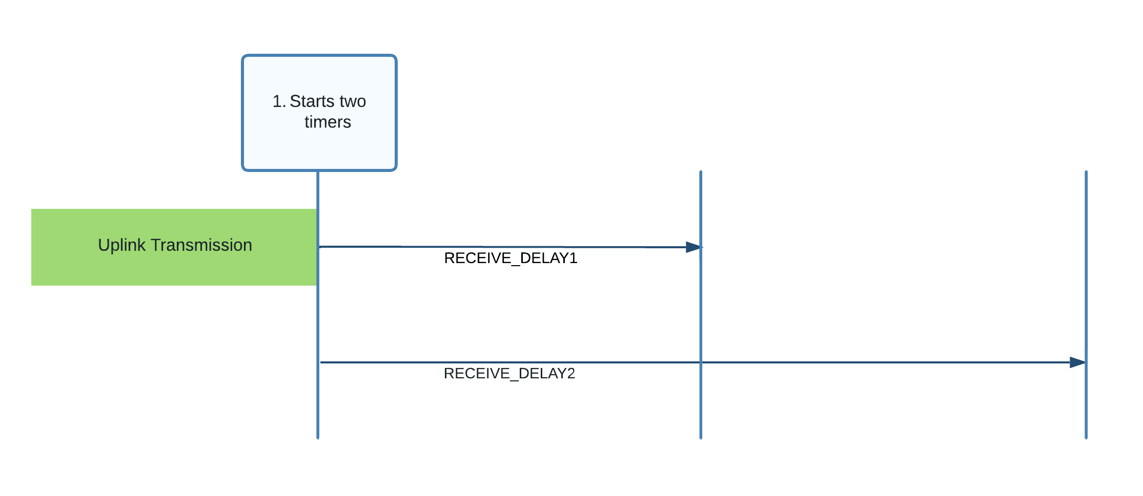
Figure 6: RECEIVE_DELAY1 and RECEIVE_DELAY2 started following uplink transmission
-
RECEIVE_DELAY1:
This is a period that begins at the end of the transmission. When this period ends, the end device begins listening for a downlink in what is referred to as receive window 1 (RX1), described below. The network server is aware of the RECEIVE_DELAY1 value, and so begins broadcast at the same time, meaning the end device begins to listen as the broadcast commences.
Following device reset, RECEIVE_DELAY1 should be set to one second, as defined in section 2.3 Default Settings of the RP002-1.0.3 LoRaWAN Regional Parameters specification.
If the end device since joined the network using OTAA, this value should have been updated to the value communicated in the RXDelay field in the join accept, as described in section Handle the Downlink Configuration Settings (DLSettings and RXDelay) of our paper In-Depth: LoRaWAN® End Device Activation.
The network server may also attempt to update this value at any time using the Del field in the MAC command RXTimingSetupReq, as described in section 5.7 Setting Delay between TX and RX (page 39) of the TS001-1.0.4 LoRaWAN® L2 1.0.4 Specification. If the end device received a RXTimingSetupReq and responded with an RXTimingSetupAns, then it should be using this Del value as the RECEIVE_DELAY1.
-
RECEIVE_DELAY2:
This is a period that begins at the end of the original uplink transmission. When this period ends, the end device begins listening for a downlink again in what is referred to as receive window 2 (RX2). The network server is aware of the value of RECEIVE_DELAY2, and so begins another broadcast at this time. RECEIVE_DELAY2 should be set to RECEIVE_DELAY1 + 1 second, as defined in section 2.3 Default Settings of the RP002-1.0.3 LoRaWAN Regional Parameters specification.
When the RECEIVE_DELAY1 period ends, the end device should open the first receive window (RX1) by beginning to listen for a downlink preamble using the data rate and channel described for RX1 in the Receive Windows section for the region it operates in, found in the RP002-1.0.3 LoRaWAN Regional Parameters specification.
The channel used for listening will vary depending on the channel used to set the uplink; the algorithm to use is provided in the specification.
The data rate used for listening depends on the data rate used to send the uplink, as well as a RX1DROffset value. The default of RX1DROffset is 0. If the end device joined the network using OTAA, the RX1DROffset should have been updated to the value communicated in the RX1DROffset bits of the DLSettings field in the join accept, as described in section Handle the Downlink Configuration Settings (DLSettings and RXDelay) of our paper In-Depth: LoRaWAN® End Device Activation. For all end devices, the network server may attempt to update the RX1DROffset value at any time using the MAC command RXParamSetupReq as described in section 5.4 Receive Windows Parameters (page 33) of TS001-1.0.4 LoRaWAN® L2 1.0.4 Specification. If the end device received a RXParamSetupReq MAC command and responded with an RXParamSetupAns, then it should be using the RX1DROffset value in the MAC command as the RX1DROffset.
The duration for which the window is open should be as long as required to detect a downlink preamble. Figure 7 shows the RX Window opened.
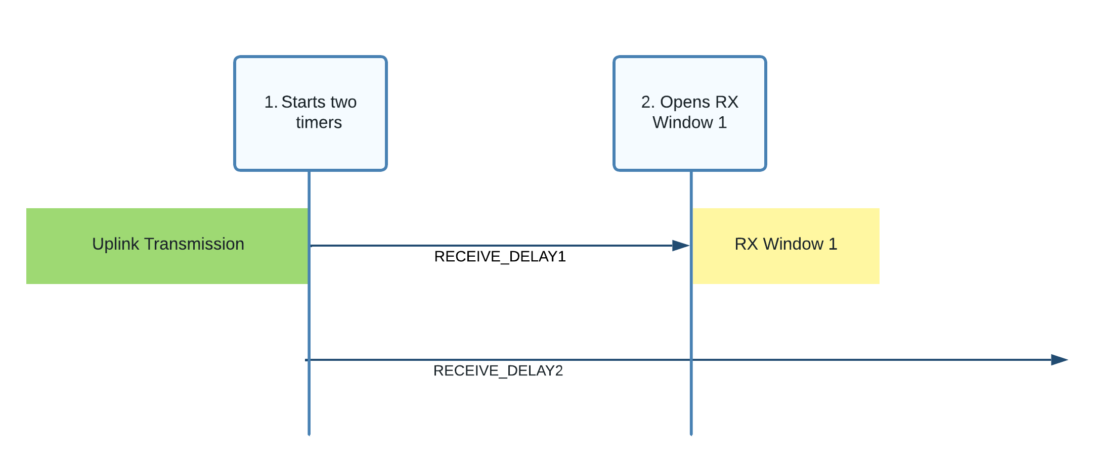
Figure 7: RX Window 1 opened following RECEIVE_DELAY1
As shown in figure 8, if a preamble is detected, the radio receiver should stay active until the downlink frame is demodulated. Once the downlink frame has been demodulated, and the end device and MIC checks described in the section Processing the Downlink Packet have passed, the process should end. The end device now does not need to open the second receive window.
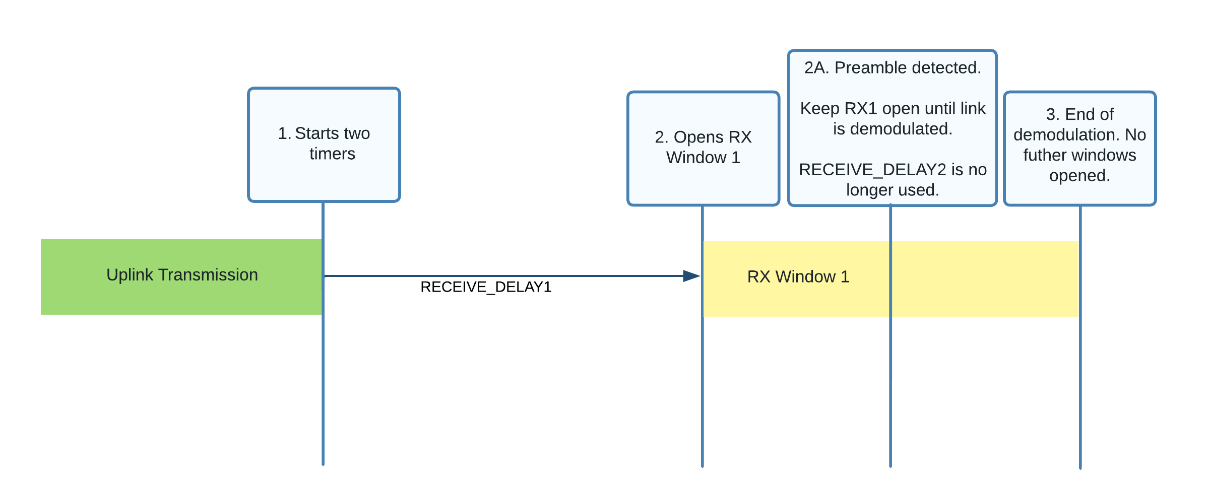
Figure 8: Preamble detected in the first receive window (RX1)
As shown in figure 9, if no preamble is detected, the window will close. When the RECEIVE_DELAY2 period has ended, providing there was no downlink accepted in receive window 1, the end device should open the second receive window (RX2) by beginning to listen for a downlink preamble using the data rate and channel described for RX2 in the Receive Windows section for the region your end device operates in within the RP002-1.0.3 LoRaWAN Regional Parameters specification. If the end device received a RXParamSetupReq MAC command and responded with an RXParamSetupAns then it should be using the RX2DataRate and Frequency values in the MAC command instead. Learn more about RXParamSetupReq in section 5.4 ‘Receive Windows Parameters (RXParamSetupReq, RXParamSetupAns)’ (page 33) of the TS001-1.0.4 LoRaWAN® L2 1.0.4 Specification.
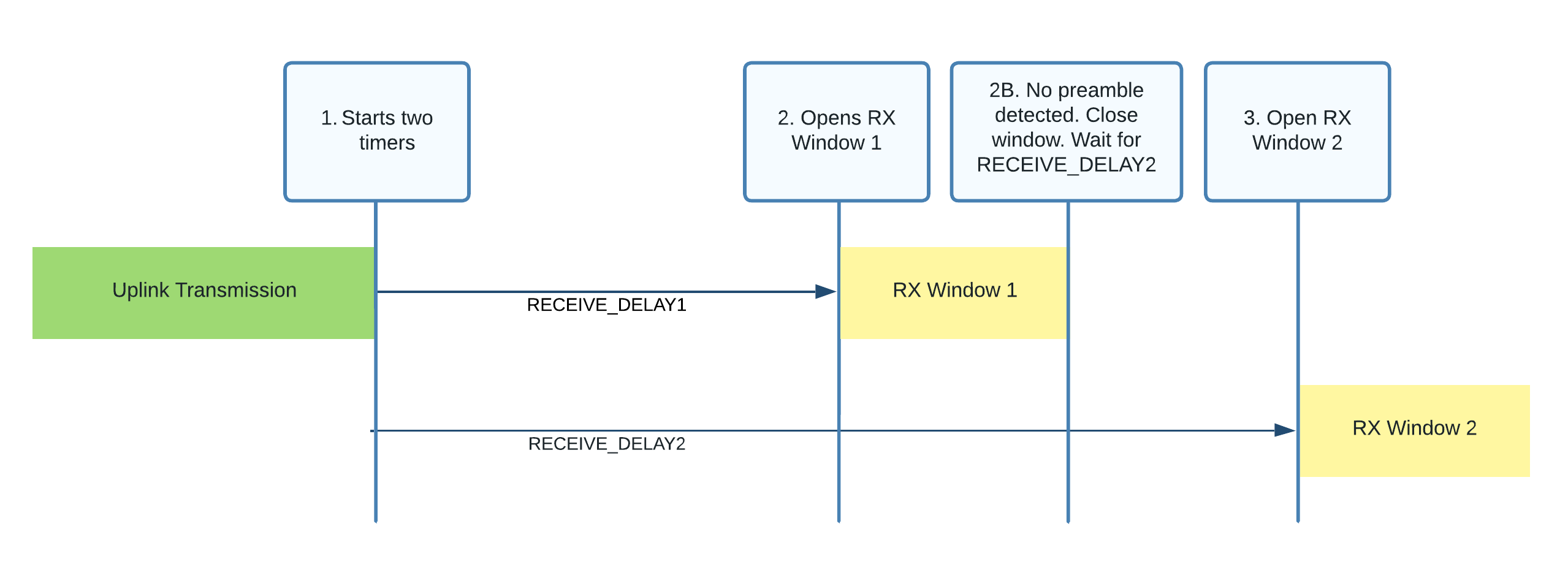
Figure 9: Opening the second receive window (RX2)
RX2 then follows the same rules as RX1. The duration for which the window is open should be as long as required to detect a downlink preamble. If a preamble is detected, the radio receiver should stay active until the downlink frame is demodulated. If no preamble is detected, the window should be closed. At this point, there are no further downlink windows opened until the next uplink is sent, or the end device moves into Class B or Class C mode.
Learn more about receive windows in section 3.3 Receive Windows (page 12) of the TS001-1.0.4 LoRaWAN® L2 1.0.4 Specification.
Process the downlink, if received, as explained in the next section Receiving Messages (Downlinks).
Receiving Messages (Downlinks)
Messages sent from a network server to an end device are referred to as downlinks. These are sent to the end device via the gateway the network server has identified as the most suitable gateway to broadcast from. This means the end device does not need to consider de-duping.
Devices operating in Class A mode only receive downlinks during the receive windows opened following an uplink, as described in Opening the Downlink Windows.
Devices that support Class B mode as well as Class A can receive additional downlinks in receive windows opened at fixed time slots. Read more in the Class B - Beacon section (page 50-73) of the TS001-1.0.4 LoRaWAN® L2 1.0.4 Specification.
Devices that support Class C mode as well as Class A can receive additional downlinks at any time. Read more in the Class C - Continuously Listening section (page 74-77) of the TS001-1.0.4 LoRaWAN® L2 1.0.4 Specification.
In this section, you learn how to receive and handle downlink packets using the LoRaWAN 1.0.4 specification.
Types of Downlinks
Downlinks may include one or both of the following types of information:
-
Application-specific settings used to modify internal settings on an end device. Unlike MAC commands which are detailed in the specification, the format of these messages and the code to implement the changes are designed and managed by you, the device manufacturer. For example, you could allow users to alter the timings at which readings are transmitted. If you have a device with multiple sensors, you could support the enabling and disabling of some of the sensors to allow users to preserve battery and only take readings from the sensors they are interested in.
-
MAC commands and MAC command acknowledgements used for LoRAWAN network administration. You will find details of each MAC command the end device may receive in our LoRaWAN MAC Commands paper.
A downlink message also contains bit fields (which are always included and can be set to either on or off) that send the following information:
-
Confirmation of receipt of a confirmed downlink message received from the end device. Confirmed downlinks are a type of downlink that requires a response from the end device.
-
Indication that there is more data to be sent down from the network server.
-
Communication that the network server can manage network settings via adaptive data rate (ADR).
Processing the Downlink Packet
A downlink message is sent in a LoRaWAN downlink packet. The LoRaWAN Packet shown in figure 10 contains a PHY Payload (PHYPayload) which contains three top-level groups of fields:
-
a MAC Header (MHDR) defining information about the type of message and its format version
-
a MAC Payload (MACPayload) containing the information being transmitted
-
a Message Integrity Code (MIC) used by the end device to verify the message was received from the same network server the device joined
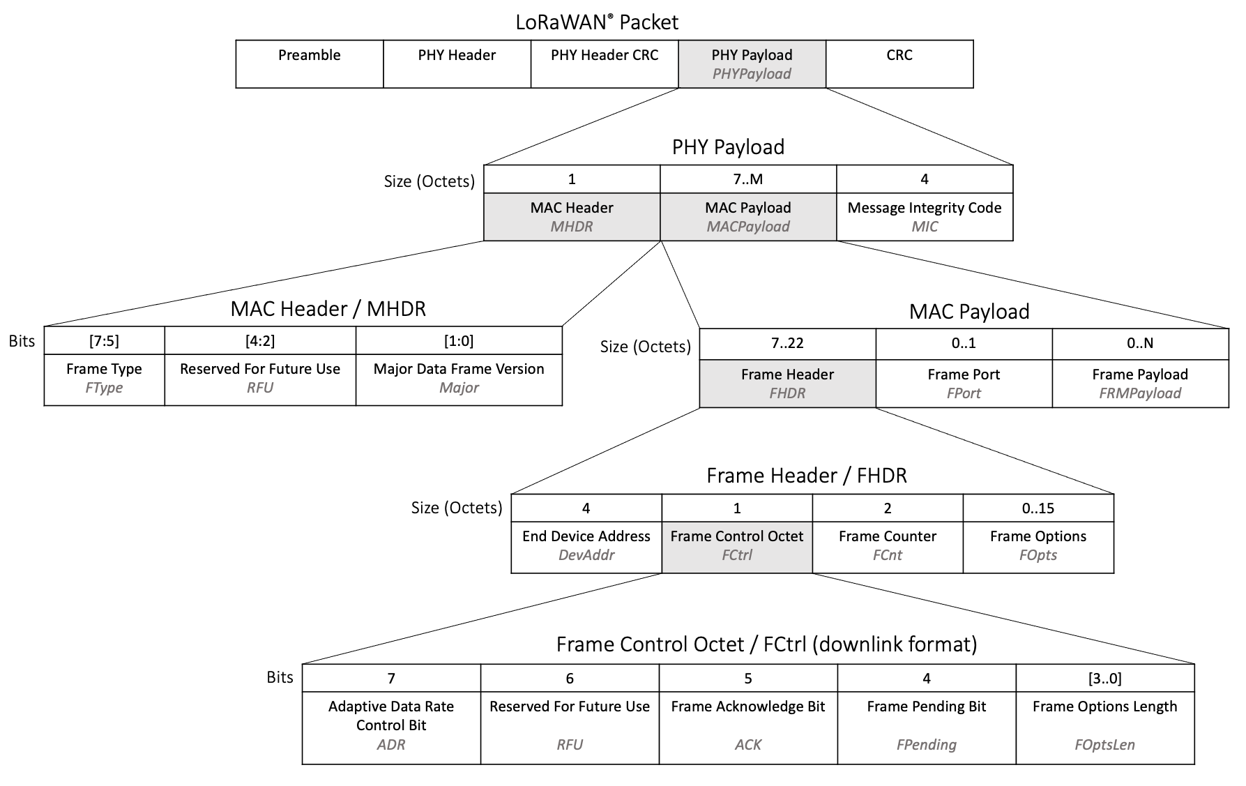
Figure 10: Fields contained in a LoRaWAN downlink packet
When the end device receives a downlink packet, the following steps should be worked through to interpret the message and obtain the data within.
Verify the End Device Address
Check that the four-octet DevAddr field in the Frame Header, indicated in figure 11, matches the DevAddr value stored in memory that was established during the end device activation process, as described in our paper In-Depth: LoRaWAN® End Device Activation.
If the end device address from the downlink does not match the stored DevAddr value, the end device must ignore the entire message as it is intended for a different device.
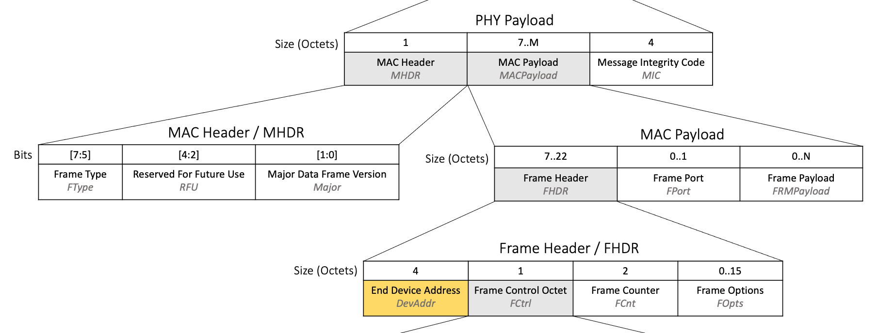
Figure 11: DevAddr field highlighted in the LoRaWAN downlink packet structure
Verify the Frame Type (FType)
Find the value in the three-bit FType field, located within the MAC Header at position [7:5], as shown in figure 12.
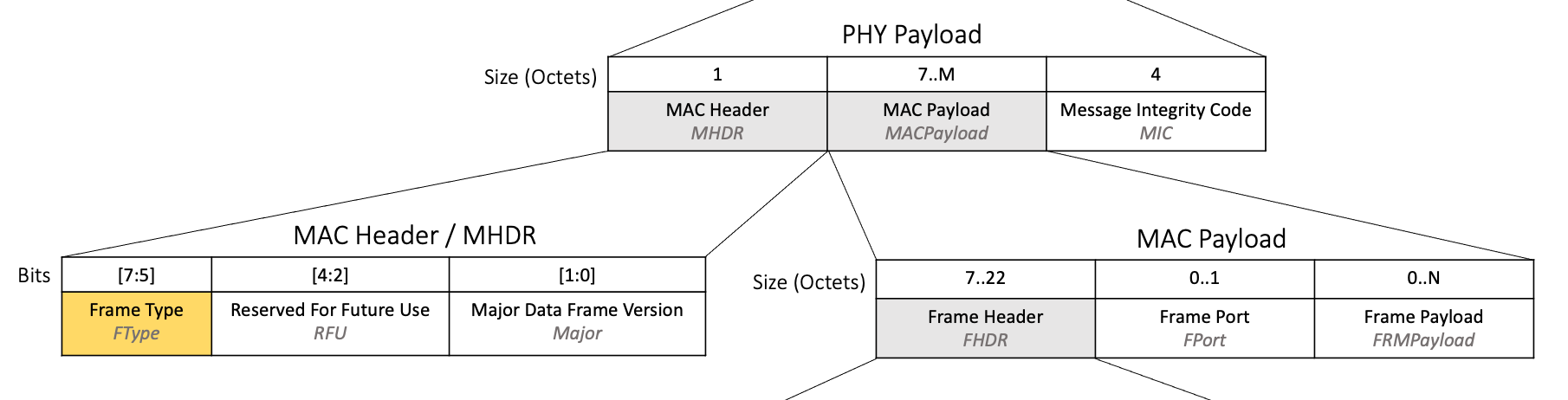
Figure 12: FType field highlighted in the LoRaWAN downlink packet structure
If FType is set to 011 (unconfirmed data downlink) or 101 (confirmed data downlink) then this message is a downlink and should be handled as described in this section.
The end device may also receive a packet with FType 001 which is a Join-Accept message. Learn more about joining a network and handling Join-Accept messages in our paper In-Depth: LoRaWAN® End Device Activation.
If FType is set to 101, and this message was received in one of the Class A receive windows, the end device must respond with an acknowledgement on its next uplink, as described in Uplink Bit Fields.
Read more in section 4.2.1, Frame types (page 16) of the TS001-1.0.4 LoRaWAN® L2 1.0.4 Specification.
Verify the Message Integrity Code (MIC)
Calculate the message integrity code (MIC) to verify the integrity of the downlink message and ensure that it has not been tampered with. Calculate the MIC over the Mac Header (MHDR), Frame Header (FHDR), Frame Port (FPort), and Frame Payload (FRMPayload) using the NwkSKey following the instructions at line 801 in section 4.4, Message Integrity Code (page 25) of the TS001-1.0.4 LoRaWAN® L2 1.0.4 Specification. The NWkSKey is obtained during end device activation.
Figure 13: Fields used to calculate the MIC
Verify that the MIC that is calculated matches the value sent down in the MIC field in the downlink. If the two MIC values do not match, the end device must ignore this message.
Verify and Update the Frame Counter (FCnt)
Find the value in the two-octet FCnt field, located inside the Frame Header within the MAC Payload, as shown in figure 14.
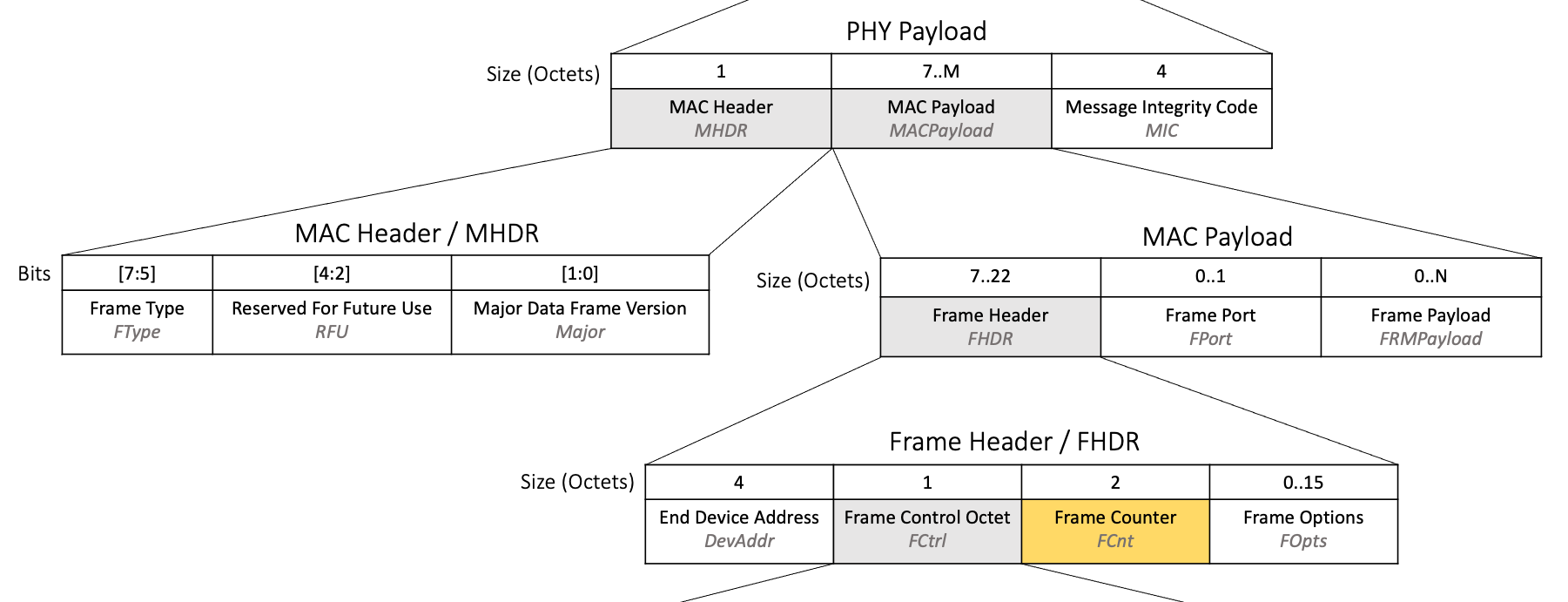
Figure 14: FCnt field highlighted in the LoRaWAN downlink packet structure
The frame counter is used to ensure that the end device does not process the same message twice, as well as to avoid being attacked by an adversary replaying old messages which could be used to manipulate an end device.
The end device must keep track of a downlink frame counter in memory, referred to in the specification as FCntDown. The value of FCntDown is set to 0 when the device first joins the network or is provisioned for activation by personalization (ABP).
If the FCnt value in the downlink is lower than or equal to the current value stored in FCntDown, this message must be ignored.
If the FCnt value in the downlink is greater than the current value stored in FCntDown stored in memory, the end device must update FCntDown to the value in FCnt and then continue to process the message as described in the next step Process the Bit Fields.
Process the Bit Fields
The following bit fields, highlighted in figure 15, are returned with each downlink inside the Frame Control Octet and should be acted upon as described.
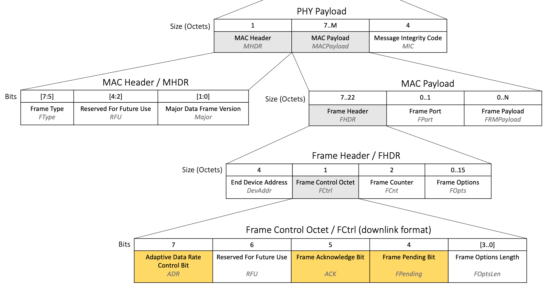
Figure 15: Bit fields highlighted in the LoRaWAN downlink packet structure
- Frame Acknowledge Bit (ACK)
-
The ACK bit is found in the Frame Control Octet inside the Frame Header within the MAC Payload, as shown in figure 15.
The ACK bit is used to acknowledge receipt of a confirmed uplink, as described in the Frame Type (FType) section of Metadata Fields.
If the end device has sent a confirmed uplink, it should be awaiting a downlink from the network server with the ACK bit set. The network server will only send the acknowledgement during the receive windows directly after the uplink was sent. If the end device is awaiting an acknowledgement, it should check that the ACK field in the downlink received in the Class A windows is set to 1. If the ACK bit is set to 1 the end device should consider the confirmed uplink responded to and execute any actions that are awaiting this confirmation.
Warning
If the end device receives a downlink following a confirmed uplink and the ACK bit is not set to 1, the uplink must have been received by the network server, but either the application data being transmitted could not be processed, or there is an issue with the network server confirming receipt of uplinks. If the receipt of the ACK is critical to the application use case, the application could resend the data in a new uplink, but should not attempt retransmission of the original uplink. The FCntUp value passed in the FCnt field should be incremented. The application should not attempt to resend the data immediately to avoid bombarding the network, but wait a period of time. You should define an upper limit to the number of attempts to send the data that should be made, to avoid continually sending the same message indefinitely in the case of a network server issue.
Read more in section 4.3.1.2, Frame acknowledge bit and acknowledgment procedure (page 20) of the TS001-1.0.4 LoRaWAN® L2 1.0.4 Specification.
- Frame Pending Bit (FPending)
-
The FPending bit is found in the Frame Control Octet inside the Frame Header within the MAC Payload, as shown in figure 15.
If the downlink message being processed was received in one of the Class A receive windows then the FPending bit set to 1 indicates that the network server has more data to send. Unless there is a good reason not to, the end device may send an empty unconfirmed uplink as soon as possible, for the purpose of opening additional downlink windows and receiving this remaining data. This empty uplink would not need to contain any MAC commands nor any application data. An example of this uplink can be seen in the appendix section Sending a Message Without MAC Commands and Application Data.
If the downlink message being processed was received in a Class B ping slot, the FPending bit is used to optimize Class B operations, as described in section 4.3.1.4, Frame Pending Bit (page 22) of the TS001-1.0.4 LoRaWAN® L2 1.0.4 Specification.
If the downlink message being processed was received in a Class C RXC window, the FPending bit should be ignored.
Warning
Take care when programming your device to ensure that the FPending bit is handled differently based on the type of receive slot the downlink arrived in. If you accidentally process the FPending bit received in a Class B ping slot or Class C window as if it were received in a Class A receive window, your end device could send unnecessary uplinks, believing there to be more data to receive when there is none.
Learn more about the FPending bit in section 16.4, Downlink Timing for Frame-Pending Frames (page 82) of the TS001-1.0.4 LoRaWAN® L2 1.0.4 Specification.
- Adaptive Data Rate Control Bit (ADR)
-
The ADR bit is found in the Frame Control Octet inside the Frame Header within the MAC Payload, as shown in figure 15.
The ADR bit is used by the adaptive data rate (ADR) feature. If the ADR bit is set to 1, this indicates that the network server can send ADR commands. If the ADR bit is set to 0, this indicates that the network is not able to use ADR currently. The actions the end device should take are explained in our paper Implementing Adaptive Data Rate (ADR).
Check the FOptsLen and FOpts Fields
MAC commands may be found in either the Frame Payload (FRMPayload) field or the Frame Options (FOpts) field. Application data may be found in the FRMPayload field. The following steps describe how to work out what these fields contain.
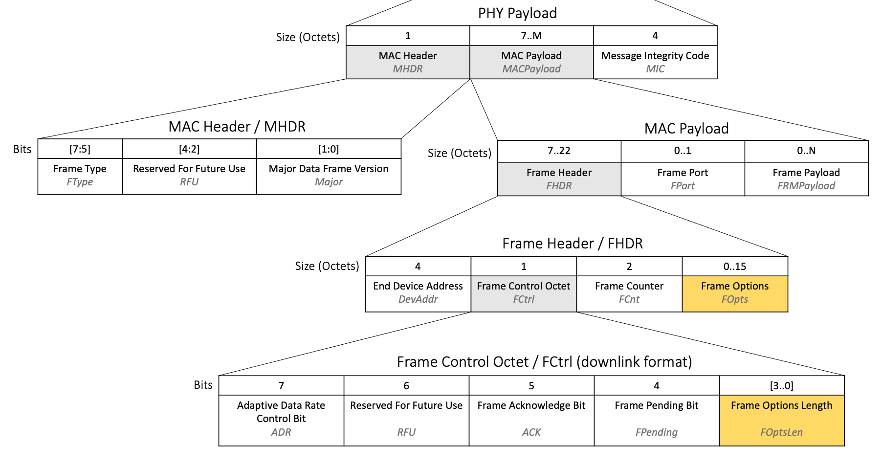
Figure 16: FOptsLen and FOpts fields highlighted in the LoRaWAN downlink packet structure
Locate the 4-bit FOptsLen field inside the Frame Control Octet within the Frame Header in the MAC Payload, as shown in figure 16.
If the FOptsLen field in the downlink is set to 0, this indicates that the FOpts field is 0 octets long, and the end device should proceed to check the FPort field described the next step. If the FOptsLen is set between 1 and 15, this indicates the FOpts exists and communicates its length in octets. The end device should read the data inside the FOpts field which will comprise of the number of octets indicated by FOptsLen and is found in the Frame Header within the MAC payload, as shown in figure 16. FOpts contains the MAC commands which the end device should only process after the FPort field has been checked, described in the following section.
Check the FPort and FRMPayload Fields
Having calculated the length of the FOpts field in the Frame Header, as described in section Check the FOptsLen and FOpts fields, the end device can now calculate the length of the entire MAC payload in the message. The end device must then check the value of the FPort octet found within the MAC Payload as shown in figure 17, if it is provided in the downlink.
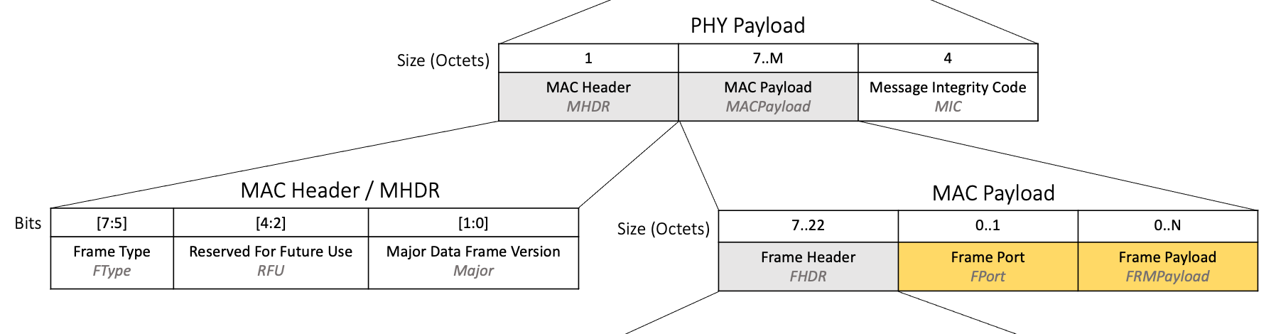
Figure 17: FPort and FRMPayload fields highlighted in the LoRaWAN downlink packet structure
If there is no FPort octet present, then there is no further data in the FRMPayload, and you can proceed to the next step Process the MAC Commands.
If FPort in the downlink is set to 0, then the accompanying FRMPayload field contains MAC commands. The FRMPayload field is found within the MAC payload as shown in figure 17. When the FRMPayload contains MAC commands, the contents of the field must be decrypted using the NwkSKey. The NwkSKey is established during device activation. Decrypt the FRMPayload by following the algorithm described in section 4.3.3 MAC frame payload encryption (page 24) of the TS001-1.0.4 LoRaWAN® L2 1.0.4 Specification. The MAC commands in the decrypted FRMPayload field should now be processed as described in the next step Process the MAC Commands.
If FPort in the downlink is set to a value between 1 and 223, then the accompanying FRMPayload contains application data. The FRMPayload field is found within the MAC payload as shown in figure 17. When the FRMPayload contains application data, the contents of the field must be decrypted using the AppSKey. The AppSKey is established during device activation. Decrypt the FRMPayload by following the algorithm described in section 4.3.3 MAC frame payload encryption (page 24) of the TS001-1.0.4 LoRaWAN® L2 1.0.4 Specification. The decrypted data is application-specific data, which we describe how to process in the upcoming section Process the Application Data.
If the FPort value is set to 224, then a MAC compliance test is being run, and the end device should respond as defined by the document LoRaWAN 1.0.4 End Device Certification Requirements for All Regions.
Process the MAC Commands
If MAC commands were found in both the FOpts field and the FRMPayload field, then the entire message should be ignored; it is not LoRaWAN compliant to include MAC commands in both fields.
If no MAC commands were found, proceed to the next section Process the Application Data.
If MAC commands were found, they should be processed according to the specification. You can read more about all the MAC commands you may receive, and find references to relevant sections of the specification, in our paper A Deep Dive into LoRaWAN® MAC Commands.
Process the Application Data
When coding your application, you will identify several scenarios that require a downlink, such as changing settings, frequency of broadcast, or triggering a real-world action such as opening or closing a valve. You can assign each of these a different FPort value, between 1 and 223, and select an encoding method. The end device must use these rules to interpret the FPort value and decrypted FRMPayload value and take the relevant actions. Learn more about designing configuration by downlink in our paper Downlink Configuration Versus Firmware Version.
If either the port or payload cannot be recognized, the message must be ignored.
Retransmitting Uplinks
There are two slightly different approaches to retransmission which depend on whether the uplink was a confirmed uplink or an unconfirmed uplink.
For both confirmed and unconfirmed uplinks, the number of times the end device retransmits the original uplink frame is defined by a value referred to as NBTrans. The default value of NBTrans should be set to 1 as defined in the specification section 5.2 Link ADR Commands (page 29) of the TS001-1.0.4 LoRaWAN® L2 1.0.4 Specification. The value of NBTrans is updated by the network using the NBTrans field in the Redundancy octet of the LinkADRReq MAC command. If the end device received an NBTrans value in a LinkADRReq MAC command and responded with an LinkADRAns, then it should be using the updated value as NBTrans. Read more in the Link Adaptive Data Rate (ADR) Commands section of our paper A Deep Dive into LoRaWAN® MAC Commands. During the ADR Backoff Procedure, the NBTrans value is reset to 1.
For unconfirmed uplinks, if no downlink message is received within the Class A receive windows, the uplink is retransmitted NBTrans times, or until a downlink is received within the Class A receive windows. Once a downlink is received, no further retransmissions should be made. It is recommended that the time between retransmissions is randomized and follows a different sequence for every end device, ensuring that groups of end devices do not all broadcast at the same time. Read more in section 3.8 Avoiding Congestion Collapse (page 16) of TR007 Developing LoRaWAN® Devices V1.0.0.
For confirmed uplinks, if no downlink message with the ACK value set is received within the Class A receive windows, and the NBTrans value is greater than 1, the end device should wait at minimum RETRANSMIT_TIMEOUT seconds after the RECEIVE_DELAY2 seconds have run out before attempting to retransmit. RETRANSMIT_TIMEOUT is defined in page 24 of the RP002-1.0.3 LoRaWAN Regional Parameters specification as a random delay between 1 and 3 seconds. In addition you may increase the delay, enforcing additional randomness per end device in that delay as described in section 3.8 Avoiding Congestion Collapse (page 16) of TR007 Developing LoRaWAN® Devices V1.0.0. Once a downlink with the ACK bit is received, no further retransmissions should be made.
For both confirmed and unconfirmed uplinks, the FCntUp value should not be incremented in memory and the FCnt value in the uplink packet should remain the same as the original transmission.
Retransmissions should be broadcast by following the same channel, data rate, and TX power rules as would be followed when sending a new uplink, continuing to iterate through the channel list and continuing through the backoff process if the end device is working through a backoff process. You must not simply use the exact same transmit settings as the previous uplink, since this would not increase the likelihood of the message getting through.
No new uplinks should be transmitted during retransmission, until retransmissions are complete or have been stopped due to the receipt of the expected downlink.
Conclusion
In this paper we have taught you how to send and receive messages following the LoRaWAN® Link Layer Specification v1.0.4 whilst implementing best practices around broadcast and retransmission to ensure your messages have the lowest possible latency whilst also respecting regulations and avoiding flooding the network with transmissions.
Read the other papers in this series: In-Depth: LoRaWAN® End Device Activation, Implementing Adaptive Data Rate, and A Deep Dive into LoRaWAN® MAC Commands.
Once you have completed the series you will be able to use LoRaMAC-node or LoRa Basics Modem with confidence, modifying settings and debugging as required. Given the required programming skills, you should also be able to code or contribute open source code for LoRaWAN network layer libraries on your preferred platform.
Further Reading
Read these technical specifications for a full understanding of LoRaWAN® 1.0.4 and related concepts:
Read these formal technical recommendations for an overview of best practices:
Read our papers on other LoRaWAN 1.0.4 concepts:
To view an example of how LoRaWAN is implemented within the LoRa® MAC layer implementation for LoRaWAN Link Layer specification 1.0.4 in C, download the LoRaMAC-Node end device stack implementation. Read our LoRaMAC-Node Hands-on Lab to learn how to use the LoRaMAC-Node reference implementation.
Appendix: Illustrative Examples of Combinations of Data Types in Messages
As discussed in sections Types of Uplinks and Types of Downlinks, there are multiple types of data that can be sent in an uplink or downlink as well as an empty message. There are different combinations of these that you could choose to send as uplinks depending on your use case and end device software. The FPort, FRMPayload, FOpts, and FOptsLen fields are set differently depending on the combinations of data types you are sending in your message. In this section we review the different configurations you need to be aware of.
Messages Containing Application Data Only
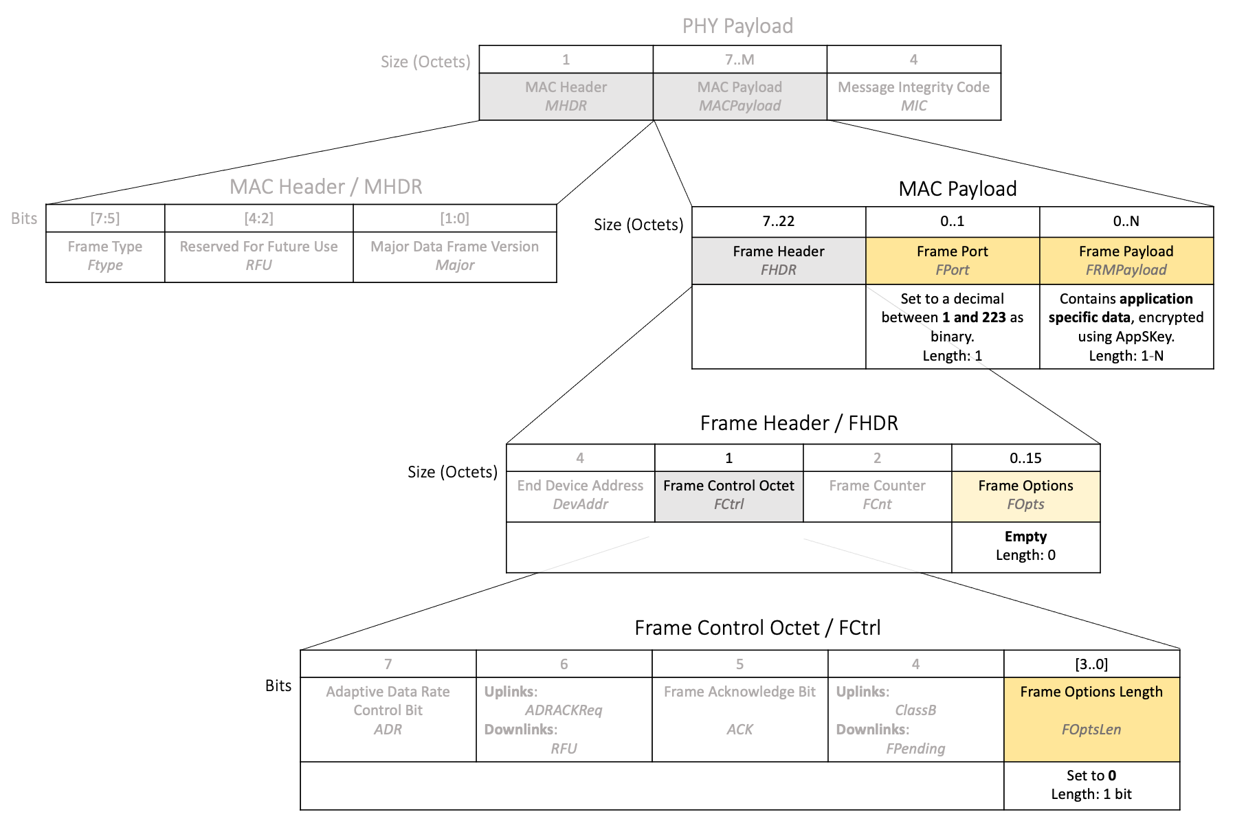
Figure 18: Use of FPort, FRMPayload, FOpts, and FOptsLen fields when sending application data only
-
the FPort is set between 1 and 223
-
the FRMPayload is set to the application data (first encrypted using the AppSKey as explained in section Frame Payload (FRMPayload) of Fields Used When Sending Application Data and MAC Commands)
-
the FOpts is left empty
-
FOptsLen is set to 0
Messages Containing MAC Commands Only
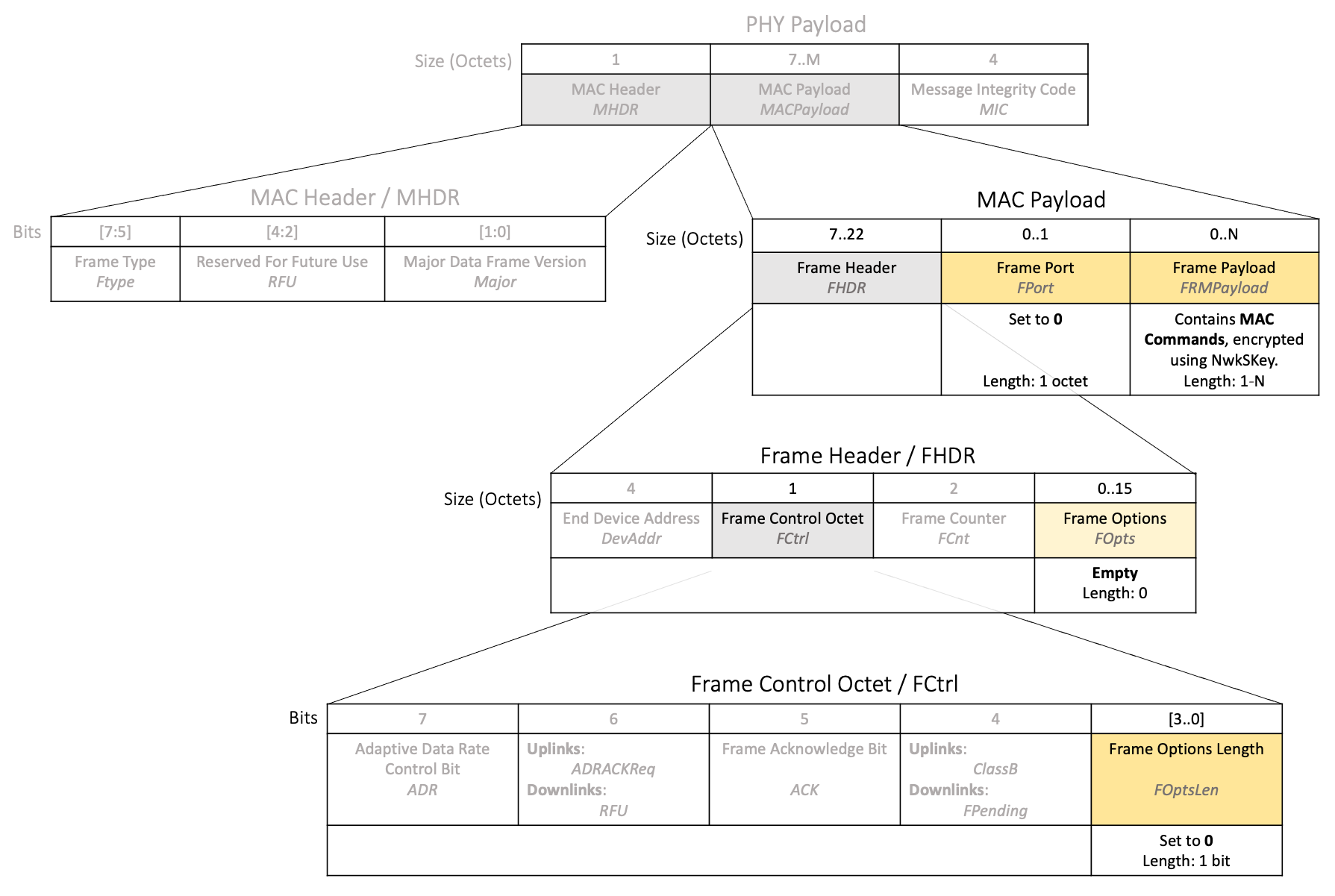
Figure 19: Use of FPort, FRMPayload, FOpts, and FOptsLen fields when sending MAC commands only
-
the FPort is set to 0
-
the FRMPayload is set to the MAC Commands (first encrypted using the NwkSKey as explained in section Frame Payload (FRMPayload) of Fields Used When Sending Application Data and MAC Commands)
-
the FOpts is left empty
-
FOptsLen is set to 0
Messages Containing MAC Commands and Application Data
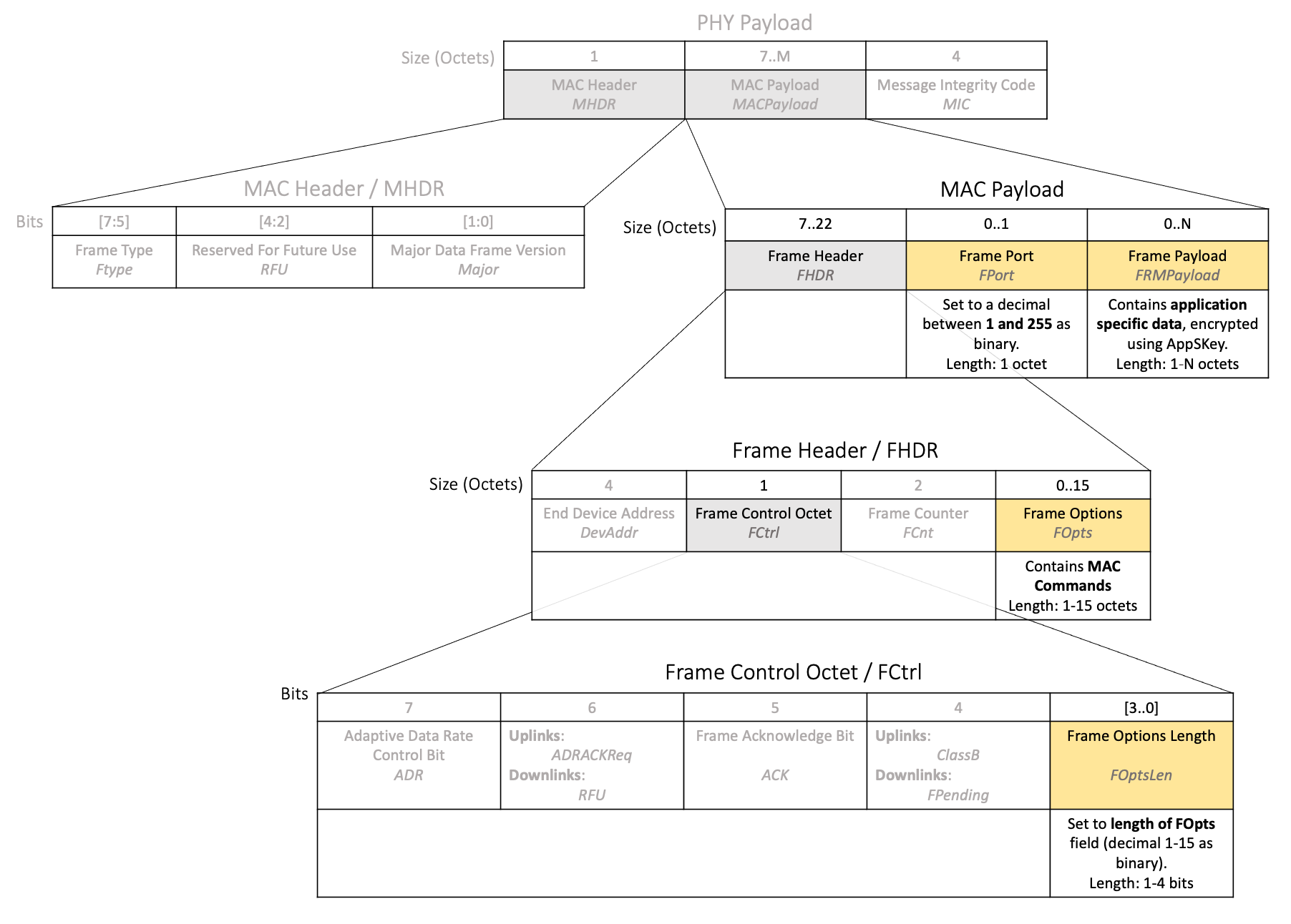
Figure 20: Use of FPort, FRMPayload, FOpts, and FOptsLen fields when sending MAC commands as well as application data
-
the FPort is set between 1 and 223
-
the FRMPayload is set to the application data (first encrypted using the AppSKey as explained in section Frame Payload (FRMPayload) of Fields Used When Sending Application Data and MAC Commands),
-
the FOpts is set to the MAC Commands
-
FOptsLen is set to the number of octets the FOpts consumes
Sending a Message Without MAC Commands and Application Data
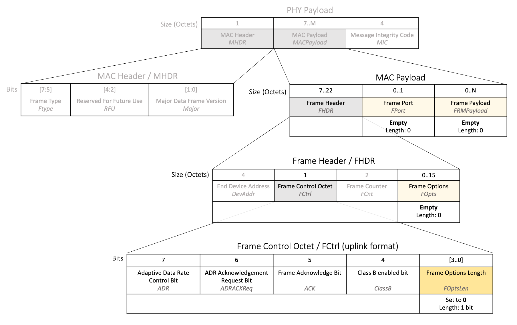
Figure 21: Use of FPort, FRMPayload, FOpts, and FOptsLen fields when sending an empty message
-
the FPort is not set
-
the FRMPayload not set
-
the FOpts is not set
-
FOptsLen is set to 0
Acknowledgement of a Confirmed Downlink
To send a confirmed downlink acknowledgement, set the ACK field to 1. Otherwise set it to 0. When the device receives a confirmed uplink acknowledgement, the ACK field will also be set to 1.
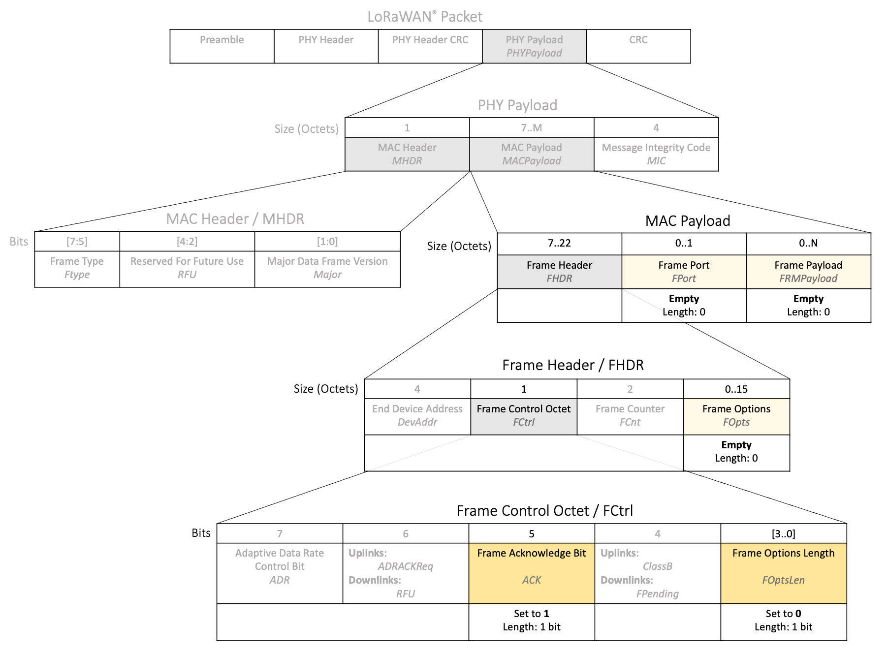
Figure 22: Use of FPort, FRMPayload, FOpts, FOptsLen, and ACK fields when sending a confirmed downlink acknowledgement or receiving a confirmed uplink acknowledgement
You can choose to send a confirmed downlink acknowledgement with an otherwise empty message, with application data only, with MAC commands only, or with MAC commands and application data together. When an end device receives a downlink with an ACK set, it must also unpack the FPort, FRMPayload, FOpts, and FOptsLen fields to see if there is any additional data.