documentation
Overview
To provide a low-cost, worldwide, single bill-of-materials solution for LoRa® operation, Semtech proposes a physical layer for the 2.4GHz global ISM band with the emulation of a LoRaWAN® protocol through an additional set of regional parameters.
For ease of understanding and application, we present the proposed parameters in exactly the same format as a conventional set of regional parameters, herein referred to as ISM2400.
Note: LoRa at 2.4GHz is not a project supported by the LoRa Alliance® or any LoRaWAN protocol projects within its working groups.
The 2.4GHz Regional Parameters: ISM2400
ISM2400 Preamble Format
The following synchronization words should be used:
|
Modulation |
Sync word |
LoRa DR |
Preamble length |
|
LoRa |
0x21 |
DR0-DR5 |
8 symbols |
|
TBD |
TBD |
TBD |
ISM2400 Frequencies
In principle, network channels can be attributed by the network operator; however, the following three default channels must be implemented. These are shown in the diagram below, together with the other frequently-occupied channels in the 2.4 GHz ISM band. Wi-Fi channels 1, 6, and 11 are shown in red and BLE advertising channels shown in blue (all frequencies are in MHz).
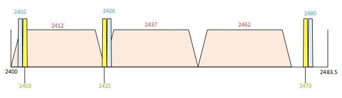
Figure1: Default Channels that Must Be Implemented
The end device must be capable of operating on these channels and the gateways should receive on them continuously.
The table below shows the ISM2400 default channels:
|
Modulation |
Bandwidth [kHz] |
Channel Frequency [MHz] |
LoRa DR |
Nb Channels |
Duty cycle |
|---|---|---|---|---|---|
|
LoRa |
812 |
2403 |
DR0 to DR7 |
3 |
TBC |
ISM2400-compatible end devices shall be capable of operating in the 2400 to 2480MHz frequency band and shall feature a channel data structure to store the parameters of at least 16 channels. The channel data structure corresponds to a frequency and the corresponding set of data rates usable on that frequency.
The first three channels correspond to 2403, 2425, and 2479MHz / DR0 to DR7. They must be implemented in every end device. These default channels cannot be modified through the NewChannelReq command; this guarantees a minimal common channel set among end devices and network gateways.
The following table lists the frequencies that shall be used by end devices to broadcast the JoinReq message. The JoinReq message transmit duty-cycle shall follow the rules described in the Retransmissions back-off chapter of the LoRaWAN specification document.
The following table shows the ISM2400 JoinReq Channel List:
|
Modulation |
Bandwidth [kHz] |
Channel Frequency [MHz] |
LoRa DR |
Nb Channels |
|---|---|---|---|---|
|
LoRa |
812 |
2403 |
DR0 – DR7 |
3 |
ISM2400 Data Rate and End Device Output Power encoding
There is no dwell time limitation for the ISM2400 PHY layer. Therefore, the TxParamSetupReq MAC command MUST be implemented in ISM2400 devices.
The following encoding is used for data rate (DR) and end device EIRP (TXPower) in the ISM2400 band:
|
Data Rate |
Configuration |
Indicative physical bit rate [bit/s] |
|---|---|---|
|
0 |
LoRa: SF12 / 812kHz |
1.2k |
|
1 |
LoRa: SF11 / 812kHz |
2.1k |
|
2 |
LoRa: SF10 / 812kHz |
3.9k |
|
3 |
LoRa: SF9 / 812kHz |
7.1k |
|
4 |
LoRa: SF8 / 812kHz |
12.7k |
|
5 |
LoRa: SF7 / 812kHz |
22.2k |
|
6 |
LoRa: SF6 / 812kHz |
38k |
|
7 |
LoRa: SF5 / 812kHz |
63k |
|
8..15 |
RFU |
|
EIRP refers to the Equivalent Isotropically Radiated Power in dBm, which is the radiated output power associated with an isotropic antenna radiating power equally in all directions, and whose gain is expressed in dBi. The following table shows the EIRP values that correspond with different TXPower levels.
|
TXPower |
Configuration (EIRP) |
|
0 |
Max EIRP |
|
1 |
Max EIRP – 2dB |
|
2 |
Max EIRP – 4dB |
|
3 |
Max EIRP – 6dB |
|
4 |
Max EIRP – 8dB |
|
5 |
Max EIRP – 10dB |
|
6 |
Max EIRP – 12dB |
|
7 |
Max EIRP – 14dB |
|
8..15 |
RFU |
By default Max EIRP shall be +10dBm to guarantee initial compliance worldwide. The maximum EIRP can be modified by the network server through the TxParamSetupReq MAC command. It should be used by both the end device and the network server once TxParamSetupReq is acknowledged by the device via TxParamSetupAns.
If the end device cannot achieve +10dBm EIRP, the device’s maximum EIRP should be communicated to the network server using an out-of-band channel during the end device commissioning process.
ISM2400 JoinAccept CFList
The ISM2400 regional parameters implement an optional channel frequency list (CFlist) of 16 octets in the JoinAccept message.
In this case, the CFList is a list of five channel frequencies for the channels three to seven, whereby each frequency is encoded as a 24-bit unsigned integer (three octets). All of these channels are usable for DR0 to DR7 812 kHz LoRa modulation. The list of frequencies is followed by a single CFListType octet, for a total of 16 octets. The CFListType SHALL be equal to zero (0) to indicate that the CFList contains a list of frequencies.
|
Size (bytes) |
3 |
3 |
3 |
3 |
3 |
1 |
|
CFList |
Freq Ch3 |
Freq Ch4 |
Freq Ch5 |
Freq Ch6 |
Freq Ch7 |
CFListType |
The actual channel frequency in Hz is (200 x Frequency), whereby values representing frequencies below 200MHz are reserved for future use. This allows setting the frequency of a channel anywhere between 200MHz to 3.35GHz in 200Hz steps. Unused channels have a frequency value of 0. The CFList is optional and its presence can be detected by the length of the JoinAccept message. If present, the CFList shall replace all the previous channels stored in the end device, apart from the three default channels. The newly-defined channels are immediately enabled and usable by the end device for communication.
Frequency Encoding in MAC Commands
The MAC commands NewChannelReq, RxParamSetupReq, BeaconFreqReq and PingSlotChannelReq all contain a three-byte field (Freq) encoding a frequency.
For the ISM2400 region, the following encoding must be used: The frequency (Freq) field is a 24-bit unsigned integer. The actual channel frequency in Hz is (200 x Freq), whereby values representing frequencies below 200MHz are reserved for future use. This allows setting the frequency of a channel anywhere between 200MHz to 3.35GHz in 200Hz steps.
The ISM2400 regional parameters only support a maximum of 16 channels. When the ChMaskCntl field is 0, the ChMask field individually enables/disables each of the 16 channels. The table below provides the ChMaskCntl values.
|
ChMaskCntl |
ChMask applies to |
|---|---|
|
0 |
Channels 0 to 15 |
|
1 |
RFU |
|
.. |
.. |
|
4 |
RFU |
|
5 |
RFU |
|
6 |
All channels ON The device SHALL enable all currently defined |
|
7 |
RFU |
If the ChMaskCntl field value is one of the values meaning RFU, the end device SHALL reject the command and unset the Channel mask ACK bit in its response.
ISM2400 Maximum Payload Size
The maximum MACPayload size length (M) is indicated in the following table. It is derived from a limitation of the PHY layer and depends on the effective modulation rate used, taking into account a possible repeater encapsulation layer. The maximum application payload length in the absence of the optional FOpt control field (N) is also given (for information purposes only). The value of N MAY be smaller if the FOpt field is not empty:
|
Data Rate |
M |
N |
|
0 |
59 |
51 |
|
1 |
123 |
115 |
|
2 |
228 |
220 |
|
3 |
228 |
220 |
|
4 |
228 |
220 |
|
5 |
228 |
220 |
|
6 |
228 |
220 |
|
7 |
228 |
220 |
|
8:15 |
Not defined |
|
If the end device will never operate with a repeater, then the maximum application payload length in the absence of the optional FOpt control field should be as indicated:
|
Data Rate |
M |
N |
|---|---|---|
|
0 |
59 |
51 |
|
1 |
123 |
115 |
|
2 |
248 |
240 |
|
3 |
248 |
240 |
|
4 |
248 |
240 |
|
5 |
248 |
240 |
|
6 |
248 |
240 |
|
7 |
248 |
240 |
|
8:15 |
Not defined |
|
ISM2400 Receive Windows
The RX1 receive window uses the same channel as the preceding uplink. The data rate is a function of the uplink data rate and the RX1DROffset, as given in the following table. The allowed values for RX1DROffset are in the [0:5] range. Values in the [6:7] range are reserved for future use. The table below shows the ISM2400 downlink RX1 data rate mapping.
|
RX1DROffset |
0 |
1 |
2 |
3 |
4 |
5 |
|---|---|---|---|---|---|---|
|
Upstream data rate |
Downstream data rate in RX1 slot |
|||||
|
DR0 |
DR0 |
DR0 |
DR0 |
DR0 |
DR0 |
DR0 |
|
DR1 |
DR1 |
DR0 |
DR0 |
DR0 |
DR0 |
DR0 |
|
DR2 |
DR2 |
DR1 |
DR0 |
DR0 |
DR0 |
DR0 |
|
DR3 |
DR3 |
DR2 |
DR1 |
DR0 |
DR0 |
DR0 |
|
DR4 |
DR4 |
DR3 |
DR2 |
DR1 |
DR0 |
DR0 |
|
DR5 |
DR5 |
DR4 |
DR3 |
DR2 |
DR1 |
DR0 |
|
DR6 |
DR6 |
DR5 |
DR4 |
DR3 |
DR2 |
DR1 |
|
DR7 |
DR7 |
DR6 |
DR5 |
DR4 |
DR3 |
DR2 |
The RX2 receive window uses a fixed frequency and data rate. The default parameters are 2423MHz / DR0 (SF12, 812kHz)
ISM2400 Class B Beacon and Default Downlink Channel
The beacons SHALL be transmitted using the following settings
|
DR |
0 |
Corresponds to SF12 spreading factor with 812 kHz BW |
|
CR |
1 |
Coding rate = 4/5 |
|
Signal polarity |
Non-inverted |
As opposed to normal downlink traffic, which uses inverted |
The beacon frame content is:
|
Size (bytes) |
5 |
4 |
2 |
7 |
3 |
2 |
|
BCNPayload |
RFU |
Time |
CRC |
Gateway-specific |
RFU |
CRC |
The beacon default broadcast frequency is 2424MHz.
The Class B default downlink pingSlot frequency is 2424MHz
ISM2400 Default Settings
The following parameters are recommended values for the ISM2400 band.
|
RECEIVE_DELAY1 |
1 s |
|
RECEIVE_DELAY2 |
2 s (MUST be RECEIVE_DELAY1 + 1s) |
|
JOIN_ACCEPT_DELAY1 |
5 s |
|
JOIN_ACCEPT_DELAY2 |
6 s |
|
MAX_FCNT_GAP |
16384 |
|
ADR_ACK_LIMIT |
64 |
|
ADR_ACK_DELAY |
32 |
|
ACK_TIMEOUT |
2 +/- 1 s (random delay between 1 and 3 seconds) |
If the actual parameter values implemented in the end device are different from these default values (for example the end device uses a longer RECEIVE_DELAY1 and RECEIVE_DELAY2 latency), those parameters MUST be communicated to the network server using an out-of-band channel during the end device commissioning process. The network server may not accept parameters different from those default values.