documentation
Stage 1: Build a Broadcast Device
In this first stage we will build the LoRa® moisture-sensing broadcasting device and configure it to send a moisture reading every 30 seconds.
Assemble the Arduino Board, Dragino Shield, and Moisture Sensor
Note
If you happen to have the Grove base shield, you can add the shield to your Arduino and plug the Grove Moisture Sensor directly into the A0 analog sensor port; otherwise follow along with these steps.
-
Place the shield next to the Arduino so that the both the shield and the Arduino have the same number of pins at the top as each other, and the same number of pins at the bottom.
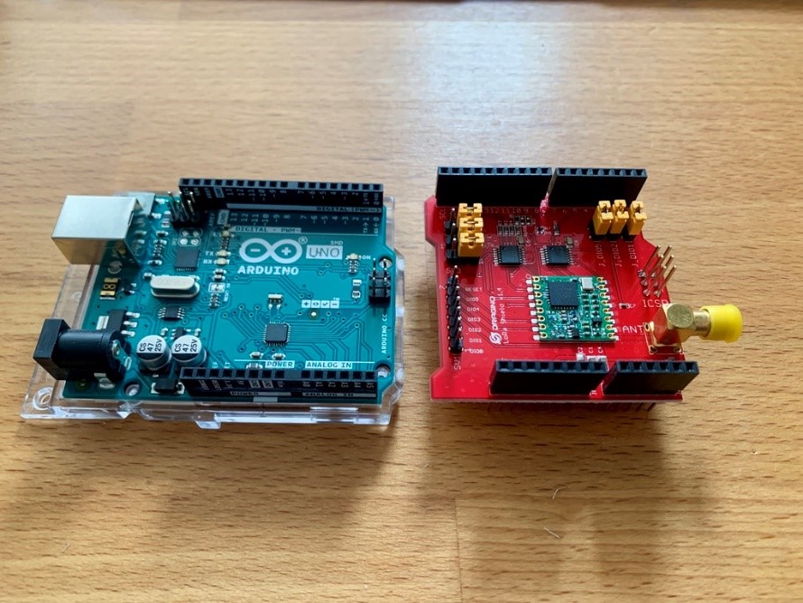
Arduino and shield side-by-side, ready to mount
- Without turning the shield, place it directly on top of the Arduino so that the pins on the shield go into the pin headers on the Arduino and push firmly down.
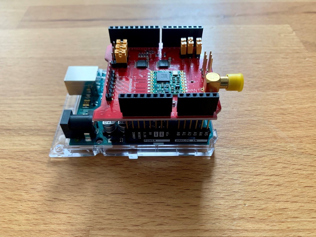
Arduino and shield, mounted
- Attach the antenna to the shield, screwing it in clockwise.

Assembled Arduino and shield, with antenna
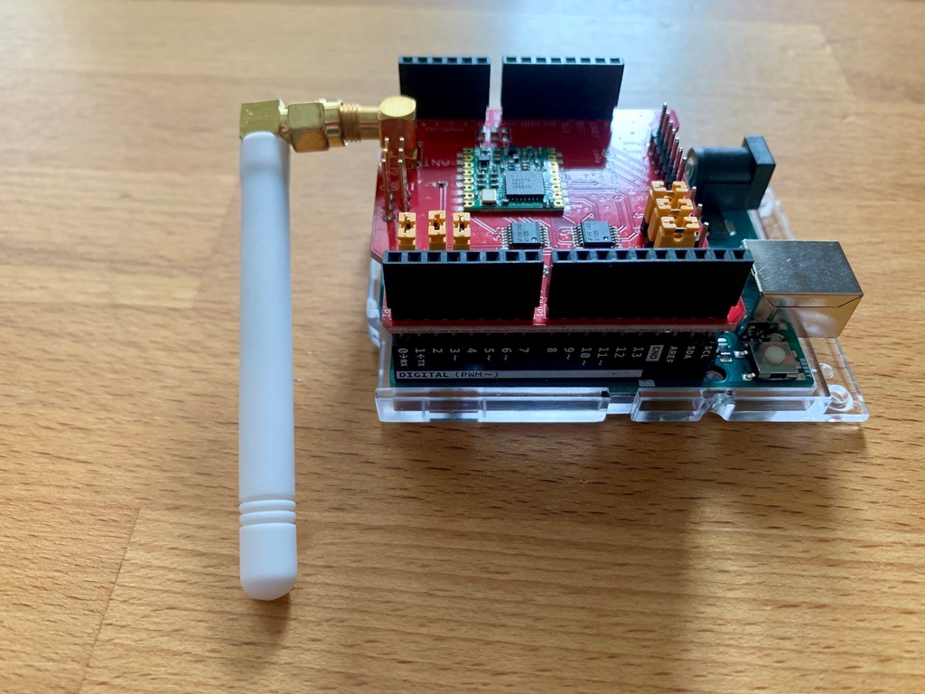
Screwing the antenna onto the shield
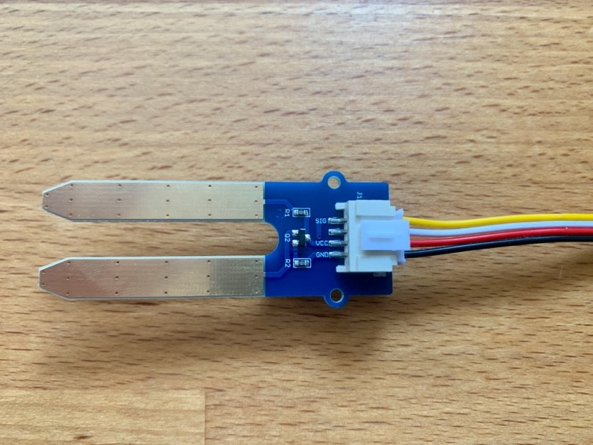
- Locate the JST-to-male jumper cable, and the Grove Moisture Sensor.
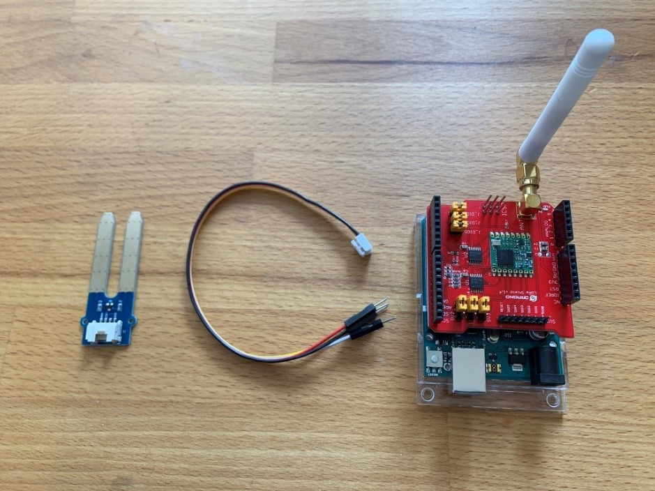
(left to right) Grove Moisture Sensor, JST to male jumper cable, assembled Arduino and shield
- Connect the male end of the jumper cable to the Grove Moisture Sensor, pushing firmly to clip it into place (Figure 9).
The Grove Moisture Sensor with male jumper connected
- At the other end of the JST-to-male jumper cable are four colored wires. We need to plug these into the terminals on the shield.
- VCC (red wire) to the 5V terminal (Figure 1)
- GND (black wire) to GND terminal (Figure 2)
- SIG (yellow wire) to an Analog terminal, A0 (Figure 3)
- The white wire is not used, we can connect it to the second GND terminal to keep it out of the way (Figure 4)
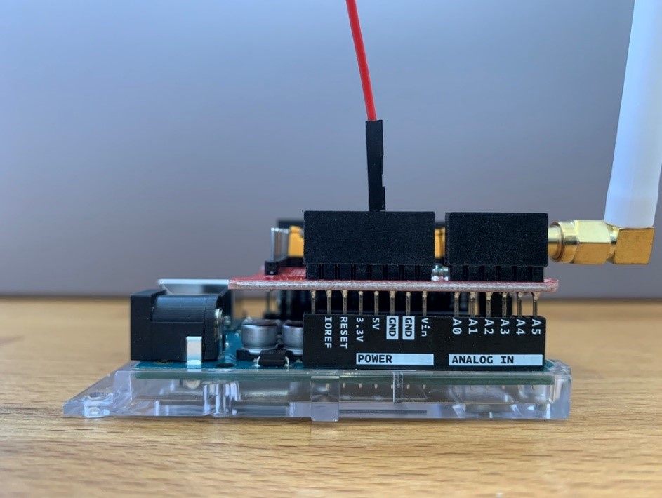
Figure 1: Red wire connected to the 5V terminal
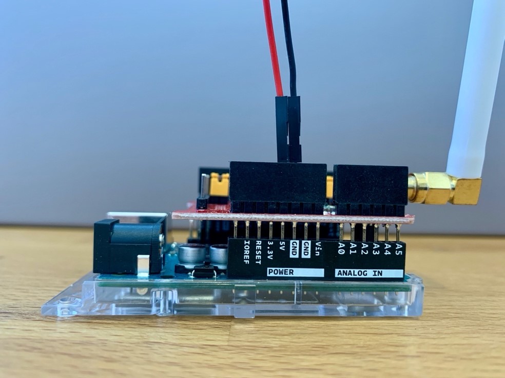
Figure 2: Black wire, connected to a GND terminal
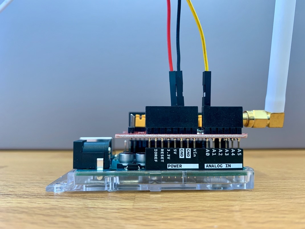
Figure 3: Yellow wire, connected to the A0 terminal
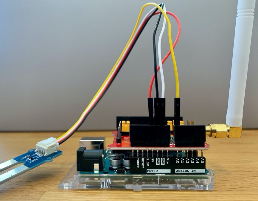
Figure 4: All wires connected, including the unused white wire
The end device is now complete.
Set Up the Arduino IDE
In this section we show you how to install the open-source library, Arduino LoRa by Sandeep Mistry. This will allow you to send and receive data using LoRa radios. Then, you will select your board.
- Download and install the latest Arduino IDE (1.8.12 at time of writing).
- Open the Arduino IDE.
-
At the Arduino IDE menu, select Sketch > Include Library > Manage Libraries.
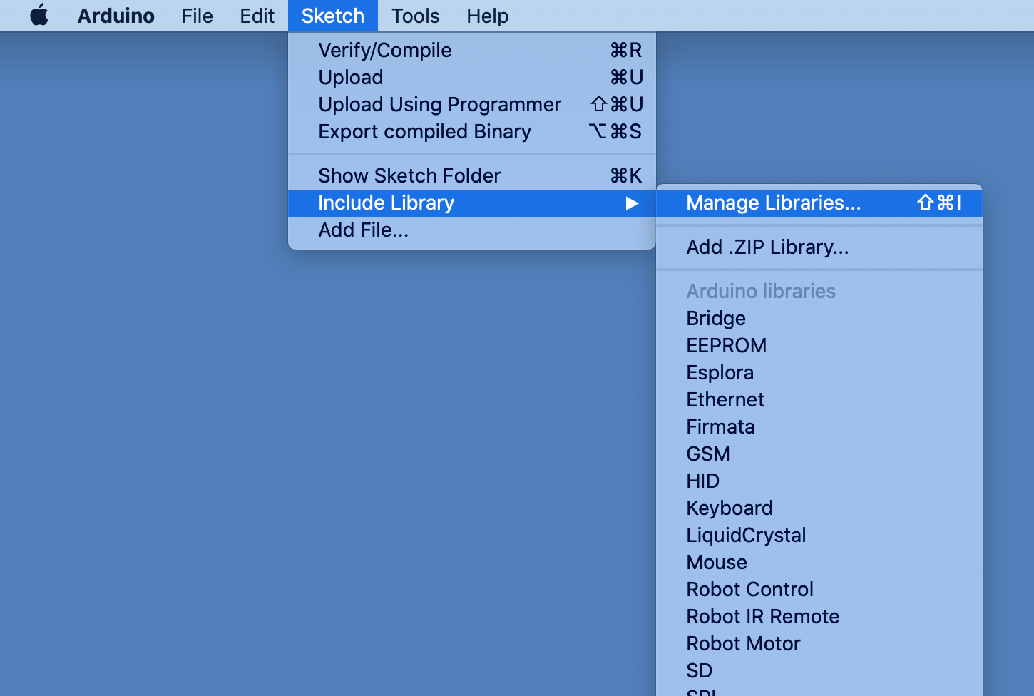
Selecting Manage Libraries in the Arduino IDE
- In the Library Manager window that opens, search for “LoRa”.
- Scroll down to find the library named LoRa by Sandeep Mistry, select the most recent version (0.7.2 at time of writing), and click Install.

Installing the LoRa library in Arduino Library Manager
- Connect the Arduino to the computer’s USB port using the USB-B cable. The green power LED illuminates on the Arduino and the shield.
- At the Arduino IDE menu, select Tools > Board > Arduino Uno (or whichever board you are using for this tutorial).
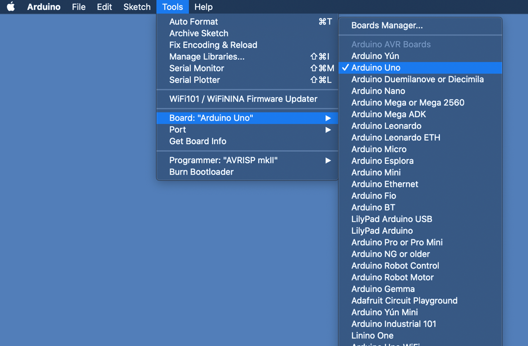
Selecting your board in the Arduino IDE
Configure the Moisture Sensor
In this section you learn how to send a moisture reading at a specified interval. If you did not purchase the second Arduino and Dragino shield, proceed to Stage 3: Connect to a Network Server.
- At the Arduino IDE menu, select File > New.
- Delete all the boilerplate code that appears in the sketch.
- Copy the code below into the sketch.
#include SPI.h
void setup() {
Serial.begin(9600);
while (!Serial);
Serial.println(LoRa Sender Test);
}
void loop() {
Serial.println(Hello.);
delay(30000);
}
Note
The
setup()function is executed first; this function sets up the console logging so that we can see the readings logged in the Arduino IDE Serial Monitor.The
loop()function logs a message every 30 seconds. - At the Arduino IDE menu bar, select Tools > Port. Select the port that indicates the model of Arduino you are using. If none of the ports are labeled, disconnect the Arduino board and reopen the menu; the entry that disappears is your board. Reconnect the board, then select the entry that had disappeared.
- At the top left of the sketch window, select the checkmark (this is the Verify icon). This will verify the sketch, which checks it for errors.
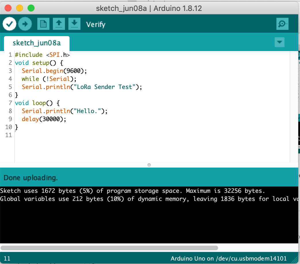
Verifying the sketch
-
At the top of the sketch window, select the right arrow (the Upload icon), to the right of the Verify icon. This will upload the sketch to the device.
You see a message that says Done uploading at the end of the sketch file window, confirming the upload has taken place.
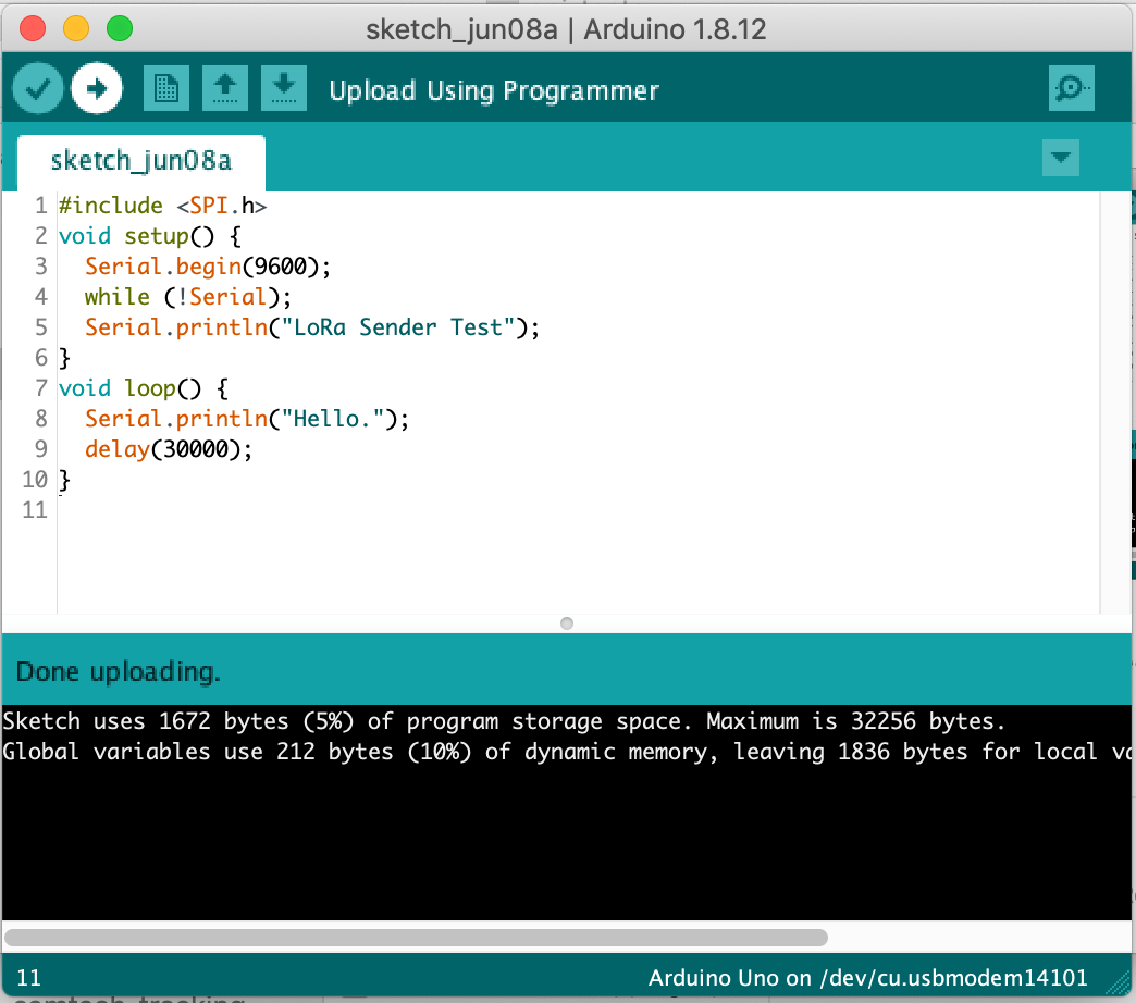
Uploading the sketch
- At the menu bar, select Tools > Serial Monitor. The Serial Monitor window will open.
- Select the 9600 baud option from the dropdown menu at the bottom-right of the Serial Monitor.
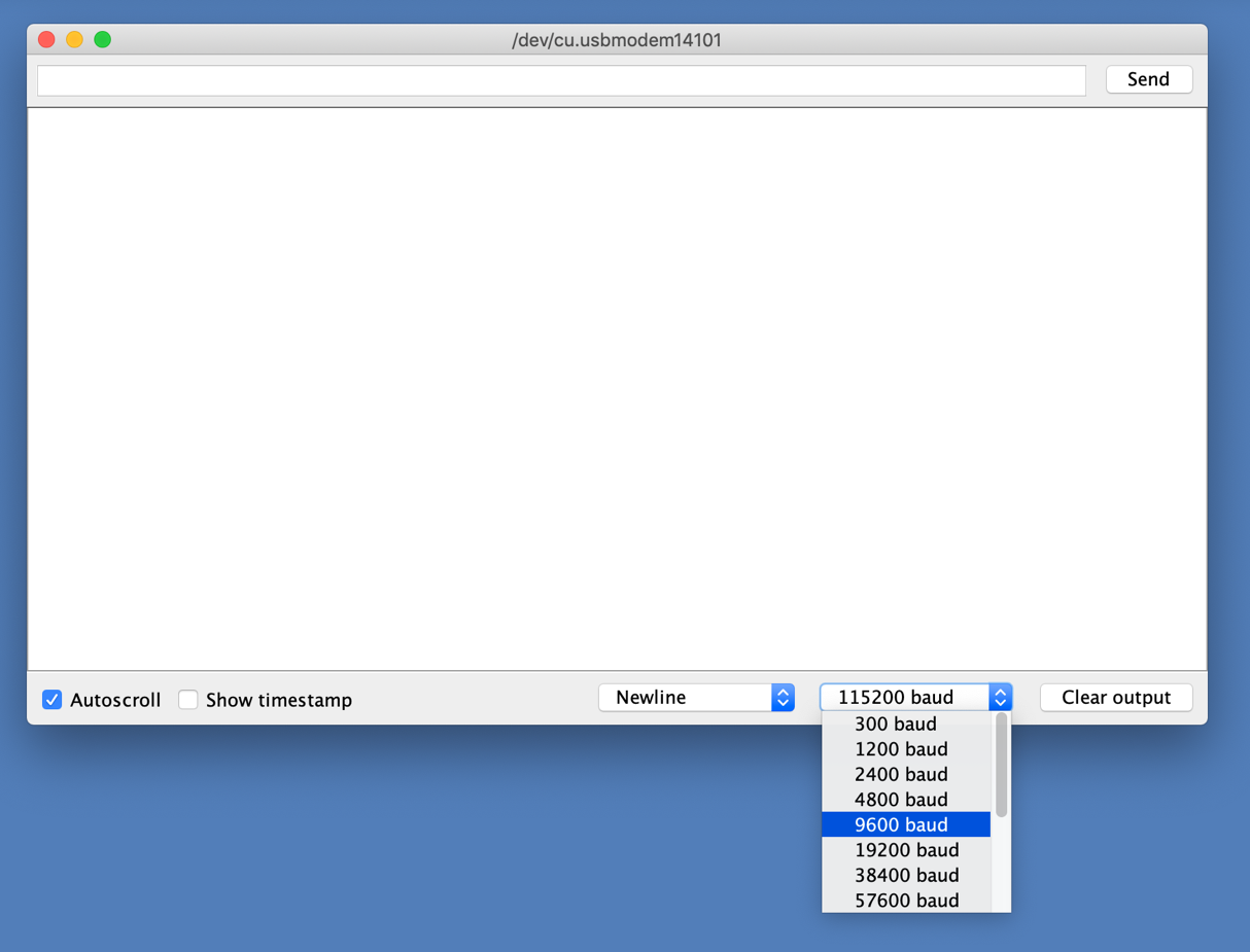
Changing the baud rate in the Serial Monitor
- If the code uploaded successfully, you see the Hello message logged to the Serial Monitor every 30 seconds.
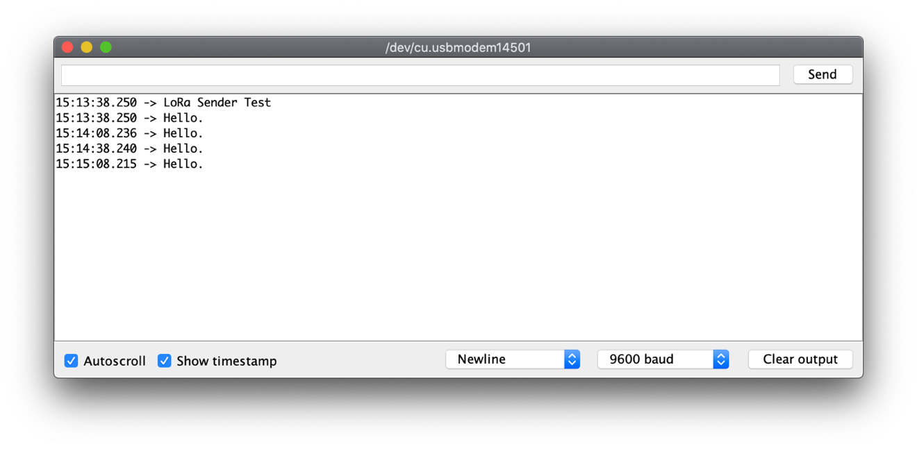
Arduino Serial Monitor showing message logging on 9600 baud.
- Add the lines marked in bold to your sketch. This will cause the sensor to send the current moisture reading to the A0 analog terminal.
#include SPI.h
#define SensorPin A0
int sensorValue = -1;
void setup() {
Serial.begin(9600);
while (!Serial);
Serial.println(LoRa Sender Test);
}
void loop() {
sensorValue = analogRead(SensorPin);
Serial.print(Reading is: );
Serial.println(sensorValue);
delay(30000);
}
Note
The declarations at the top of the sketch define which analog pin the sensor is connected to and will set an initial value of
-1.Within the loop, the
analogRead()function gets the current reading from the moisture sensor via the sensor pin. The moisture sensor reading prints out to the Serial Monitor. - Verify and upload the new sketch to the Arduino, then open the Serial Monitor. You will see the real-time sensor value logged every 30 seconds.

Arduino Serial Monitor showing sensor readings
- Test the Soil Moisture sensor by locating two pots of soil, making one pot of soil damp and keeping one dry. If you do not have a pot of soil, use a shallow glass of water, but take care to only insert the metal coated probes into the water and keep liquids away from the top of the sensor above the prongs, as well as away from the Arduino, to avoid potential short circuits.
- Insert the sensor into the pot of moist soil. The sensor measures across the whole length of the probes, so make sure you push the majority of the length of the probe into the soil to get a good reading.
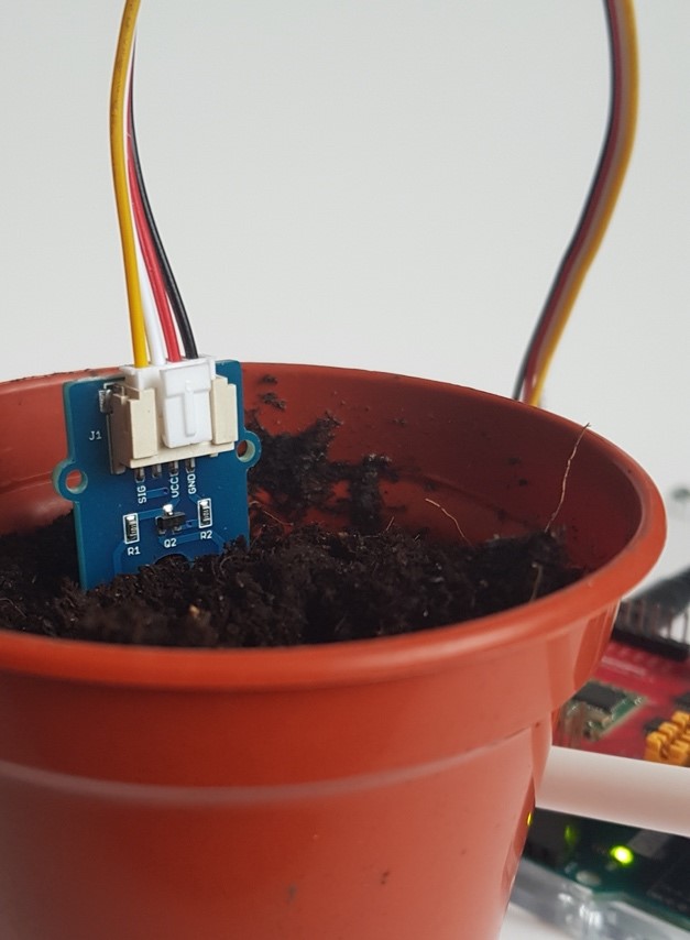
Testing the assembled moisture sensor
-
Inspect the Serial Monitor to see the readings. The higher the number, the more moisture has been detected in in the soil.
Suggested meanings for the Grove Moisture Sensor measurement are:
- 0-299: the sensor is in dry soil
- 300-699: the sensor is in humid soil
- 700-950: the sensor is in waterlogged soil or water
- Move the sensor to a drier pot of soil and see the numbers decrease in the Serial Monitor.
- Add the following bolded lines of code to the sketch to place this reading into a LoRa packet that the device sends every 30 seconds.
#include SPI.h
// Add the LoRa library
#include LoRa.h
#define SensorPin A0
int sensorValue = -1;
void setup() {
Serial.begin(9600);
while (!Serial);
Serial.println(LoRa Sender Test);
// Initalize the LoRa radio on the shield.
// NB: Replace the operating frequency of your shield here.
// 915E6 (US902-928) / 868E6 (EU863-870) / 433E6 (EU433)
if (!LoRa.begin(868E6)) {
Serial.println(Starting LoRa failed!);
while (1);
}
}
void loop() {
sensorValue = analogRead(SensorPin);
Serial.print(Reading is: );
Serial.println(sensorValue);
// Transmit the LoRa packet
LoRa.beginPacket();
LoRa.print(sensorValue);
LoRa.endPacket();
delay(30000);
}Note
The LoRa library is included with the line
#include lora.h.The LoRa radio on the Dragino shield is initialized with
LoRa.begin.The LoRa packet containing the sensor value transmits using
LoRa.beginPacket,LoRa.printandLoRa.endPacket. - Update the variable in your code (shown in bold below) to match the variable representing the frequency plan for your region. For frequency plan EU863-870/EU868 this is
868E6, for US902-928/US915:915E6, for EU433:433E6.…
Serial.println(LoRa Sender Test);
// Initalize the LoRa radio on the shield.
// NB: Replace the operating frequency of your shield here.
// 915E6 (US902-928) / 868E6 (EU863-870) / 433E6 (EU433)
if (!LoRa.begin(868E6)) {
Serial.println(Starting LoRa failed!);
while (1);
}
…
- Verify and upload the sketch to the Arduino.
-
Check the Serial Monitor to verify the device is still logging readings every 30 seconds.
Well done! – You now have a working wireless LoRa device which broadcasts a soil moisture reading at regular intervals.
If you purchased a second Arduino and shield, continue to Stage 2: Build a Receiver Device, to build a LoRa device to receive the message locally.
If you did not purchase a second Arduino and shield, continue to Stage 3: Connect to a Network Server, to setup your gateway and receive the message via the cloud.